Assessing the Q of a half wave dipole antenna system explained that Q can be a valuable indicator of antenna system health.
This article uses a recently published VSWR curve for a 15m half wave dipole antenna system as an example to demonstrate the technique.
The following graph is from a Sark100 style antenna analyser, and it is quite a poor start to diagnostics, but using it draws out what is desired for further analysis.
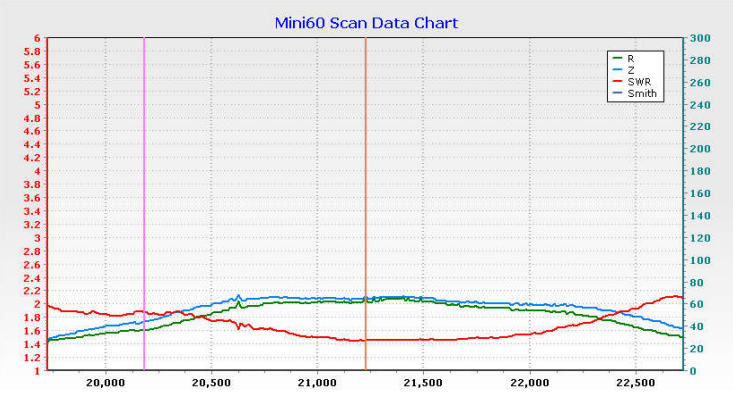
Above, the captured VSWR50 sweep.
With very careful work, I have extracted some key points:
- minimum VSWR is 1.44; and
- VSWR=1.8 at 20.446 and 22.346MHz giving VSWR(1.8) bandwidth as 1900kHz.
Note that although this example uses an antenna analyser, we are only using three points from the VSWR curve and the above data points could be captured with an ordinary VSWR meter.
Lets plug those numbers into Calculate Antenna Q from VSWR bandwidth measurement.
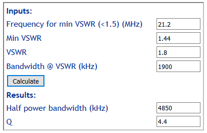
Above, the calculated Q is 4.4, which is very low for a half wave dipole system and indicates a fault.
Conclusions
The source VSWR sweep was rather poor, it was relatively flat and bumpy and small scale so difficult to read directly and was digitised to get better reading accuracy.
Though reading issues and the class of instrument give rise to larger uncertainty, the indicated Q falls so far short of the 10-13 range that is typical of good half wave wire dipole antenna systems that it is very likely that the system is faulty and bears more detailed investigation.