This project is a data logger accessory for Lou Destefano’s (VK3AQZ) RF Power Meter kit (RFPM1).
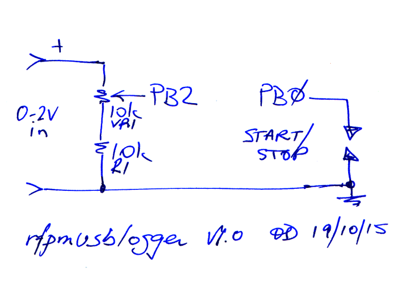
The RFPM1 develops an analog signal 0-2000mV corresponding to 0-100dB input power range, -85-16dBm. The module described here produces a digital output scaled -85.0 to 15.0 for 0-2000mV input.
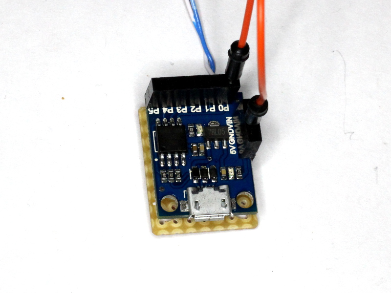 The hardware is based on a clone of the Digispark ATTiny85 USB development board, about A$3 incl shipping on eBay. Differently to the original Digispark, the board above has a micro USB connector on board. The vero ‘mother board’ carries a resistor and 10t pot for calibration adjustment.
The reference voltage on these chips has fairly wide tolerance, so the 2000mV input is divided down to 1500-1800mV FS prior to sampling by the 10bit ADC with nominal 2.56V reference. The digital value is multiplied by 1.5 and then 850 subtracted to give an intercept value equivalent to -85dBm. The system is calibrated by adjusting the pot for a reading of 15.0 from 2000mV DC input.
With the scaling factor, 15.0 (dBm) is produced for a nominal voltage at the ADC input of (15.0+85)*10/1.5/1023*2.56=1668mV.
The module is self powered, and has a two wire connection to the 0-2000mV signal, and a two wire connection to a momentary switch for turning logging on and off.
The firmware is a variation on Easylogger, with changes for the pinout used on Digispark boards and scaling and offset to suit the application. The Easylogger device looks like a keyboard (HID) and in use, will key observations every 1s into the current window, eg a spreadsheet or text editor. It is possible to write a batch script to collect the measurements and add a timestamp to each data row before writing it to a file.
carries a resistor and 10t pot for calibration adjustment.
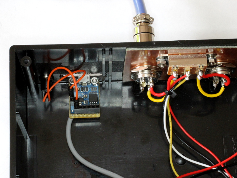
Above is a pic of the data logger fitted to the case of the RFPM1. A hole in the case provides access to the USB socket and calibration pot.

Above is a block diagram of a measurement configuration. In this case the PC controls the IC7410 transceiver, and logs the data from the RFPM1 via its USB connection. For more details of this application and sample scripts, see Return Loss sweep using IC7410, RL bridge, and RFPM1.
Source code repository: rfpmusblogger.
Completion of the project awaits some hardware (on a slow boat from China) to secure the module inside the RFPM1 case.
More on completion…