Walt Maxwell (W2DU) made much of conjugate matching in antenna systems, he wrote of his volume in the preface to (Maxwell 2001 24.5):
It explains in great detail how the antenna tuner at the input terminals of the feed line provides a conjugate match at the antenna terminals, and tunes a non-resonant antenna to resonance while also providing an impedance match for the output of the transceiver.
Walt Maxwell made much of conjugate matching, and wrote often of it as though at some optimal adjustment of an ATU there was a system wide state of conjugate match conferred, that at each and every point in an antenna system the impedance looking towards the source was the conjugate of the impedance looking towards the load.
This is popularly held to be some nirvana, a heavenly state where transmitters are “happy” and all is good. Happiness of transmitters is often given in online discussion by hams as the raison d’être for ATUs .
(Maxwell 2001 24.5) states
To expand on this definition, conjugate match means that if in one direction from a junction the impedance has the dimensions R + jX, then in the opposite direction the impedance will have the dimensions R − jX. Further paraphrasing of the theorem, when a conjugate match is accomplished at any of the junctions in the system, any reactance appearing at any junction is canceled by an equal and opposite reactance, which also includes any reactance appearing in the load, such as a non-resonant antenna. This reactance cancellation results in a net system reactance of zero, establishing resonance in the entire system. In this resonant condition the source delivers its maximum available power to the load. …(1)
KL7AJ posed this quick quiz on QRZ.com:
You have an H.F. transmitter, some low loss transmission line, a good antenna tuner, and an antenna analyzer. And an antennna
With your antenna analyzer, you look at the input impedance of the transmission line leading to your antenna, and you read 50-75j ohms. You disconnect the antenna analyzer, and connect your antenna tuner to the line, and your transmitter, and adjust the tuner so the transmitter sees a perfect 1:1 match. You shut off the transmitter, and without disturbing the antenna tuner adjustments, you connect a 50 ohm resistor to the INPUT terminals of the antenna tuner. You connect your antenna analyzer to the OUTPUT terminals of the antenna tuner. What will the antenna analyzer read?
Reflections disciples will instantly answer with the complex conjugate, 50+j75Ω, That was the response that KL7AJ acknowledged as correct, but is it simply the complex conjugate in real antenna systems such as in the question?
A real world example
So, let’s try out KL7AJ’s challenge… but mathematically where measurement error is eliminated. In this case, we are focussing on just one antenna system component, the ATU which itself is a quite simple passive network.
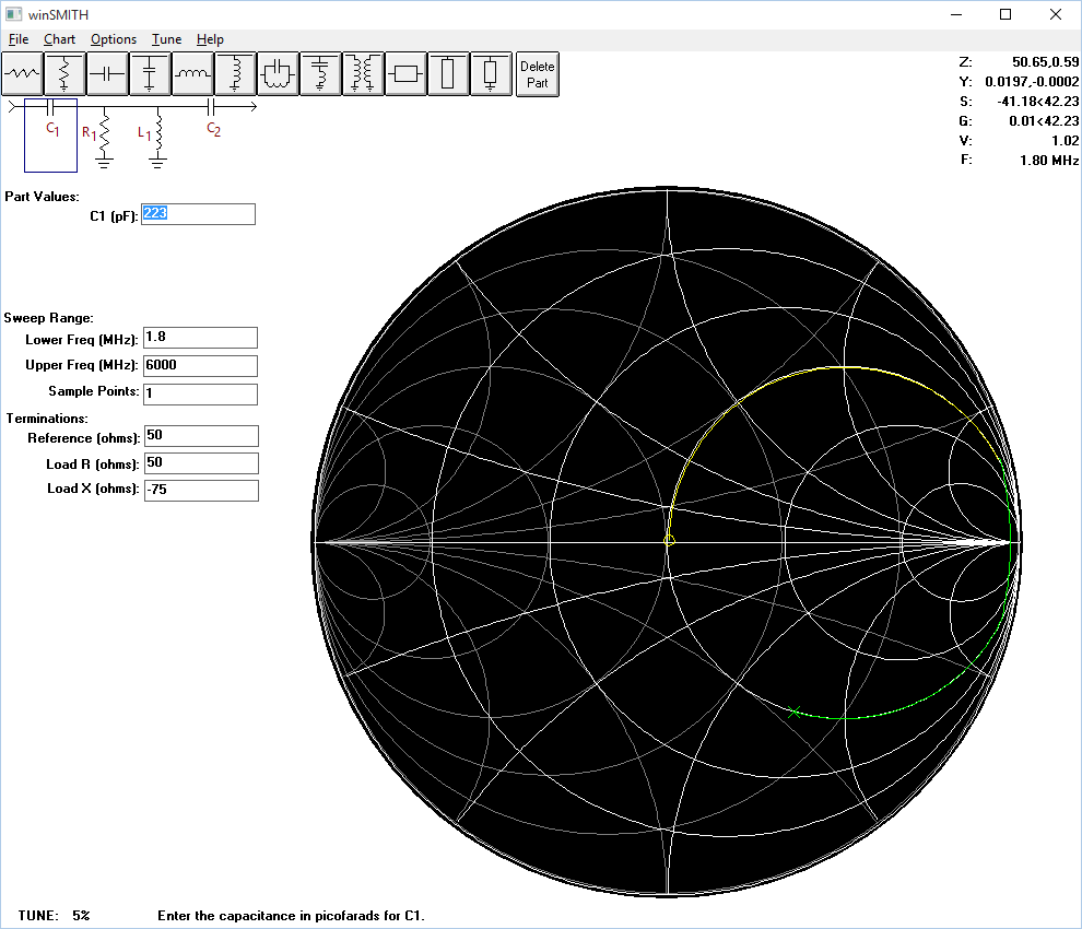
Above is the Smith chart matching solution to a T-tuner using lossless capacitors and an inductor with Q=100 (realistic). Though lossless capacitors have been used, in a typical tuner the inductor loss dwarfs capacitor loss and so the results would be almost the same as if capacitor Q was say 2000.
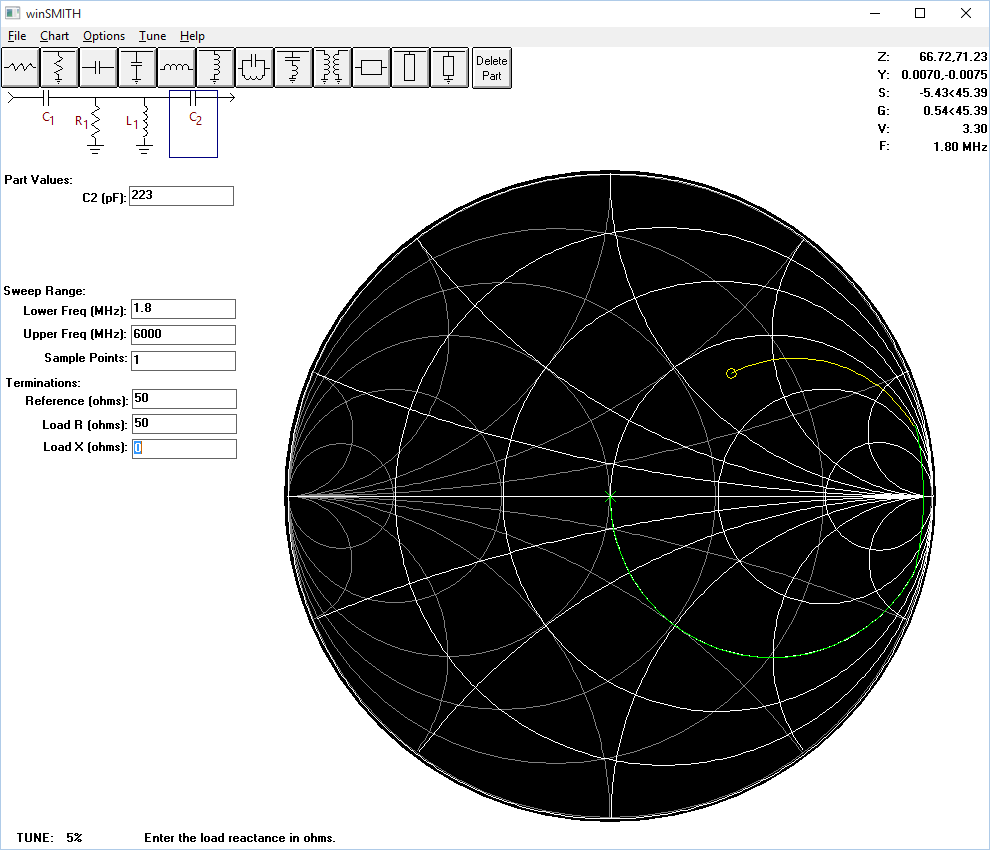
Above is the network transposed and with load of 50+j0Ω. The input Z is 66.72+j71.23Ω., significantly different to 50+j75Ω. as predicted by Maxwell.
It takes only one valid example to show Maxwell’s statement is wrong.
Why is it so
(Maxwell 2001 24.5) relies on a quotation:
If a group of four-terminal networks containing only pure reactances (or lossless lines) are arranged in tandem to connect a source to its load, then if at any junction there is a conjugate match of impedances, there will be a conjugate match of impedances at every other junction in the system. (Everitt 1937 243) and (Everitt and Anner 1956 407)
The problem is that Maxwell silently dropped from his statement (1) above the requirement that networks and lines must be lossless, and the example calculated here shows that Maxwell’s proposition does not apply to the real world networks that has loss.
Recourse to simple linear circuit analysis will reveal that lossy networks do not have the property Everitt ascribed to lossless networks.
Walt Maxwell’s congugate mirror
does not apply in the real world, and the concept is of no use in understanding real world antenna systems.
Thevenin equivalent source impedance of a transmitter
KL7AJ’s question might imply that a 50Ω source is typical of a real world transmitter.
Walt’s system wide conjugate match concept of course implies that where an ATU was adjusted for VSWR50=1, the transmitter is a Thevenin source with Zs equal to the conjugate, that Zs=50+j0Ω.
The issue is that typical ham SSB HF transmitters are not well represented by a Thevenin equivalent circuit at all, much less that Zs=50(+j0)Ω (Duffy 2010).
There is a difference between a transmitter’s required nominal load impedance and its Thevenin equivalent source impedance, or whether it can even be validly represented by a Thevenin equivalent circuit.
It is possible to design a transmitter to have a tightly controlled Thevenin equivalent source impedance of 50+j0Ω and although not easy, it is done in some specialised commercial and some ham transmitters for specific benefits, but it does not happen by accident, especially as a simple consequence of tuning of a PA as Walt suggested.
Conclusions
- KL7AJ’s quick quiz demonstrates the level of understanding of the technology in the modern ham community.
- Online discussions tend to pay homage to folk lore as ham radio transforms from a once principally technical hobby to a principally social non-technical activity where folk lore reigns.
- Some authors pander to the yearning for explanations that are appealing principally because they are simple, but that does not make them valid or even good explanations but it does make them popular.
- Popularity does not of itself make facts, not even in ham radio.
References
- Duffy, O. Jun 2010. Is Zs of a HF ham tx typically 50+j0?. VK1OD.net (offline).
- ———. Mar 2013. The failure of lossless line analysis in the real world. https://owenduffy.net/transmissionline/folla/index.htm.
- Everitt, W L. 1937 Communications Engineering, 2nd ed. New York: McGraw-Hill Book Co.
- Everitt, W L, and Anner, G E. 1956 Communications Engineering, 3rd ed. New York: McGraw-Hill Book Co.
- Maxwell, Walter M. 2001. Reflections II. Sacramento: Worldradio books.