Flashing LED driver using an ESC described a LED driver for an animal deterrent using a repurposed brushless DC motor electronic speed controller.
This article describes a simpler implementation based on a Chinese 8051 architecture microcontroller, the STC15F104E.
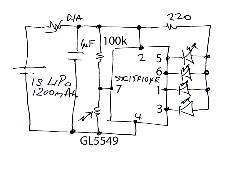
Above, the schematic. A very simple circuit with just a handful of electronic components (one capacitor, two resistors, one LDR, one Polyswitch, 4 x LEDs and the MCU).
It is powered directly from a 1S LiPo battery (ie single cell at 3.6-4.3V). The MCU shuts down at 3.8V to reduce load on the battery, the LDR allows the flasher to cease flashing (and so reduce power) during daylight (>30lx).
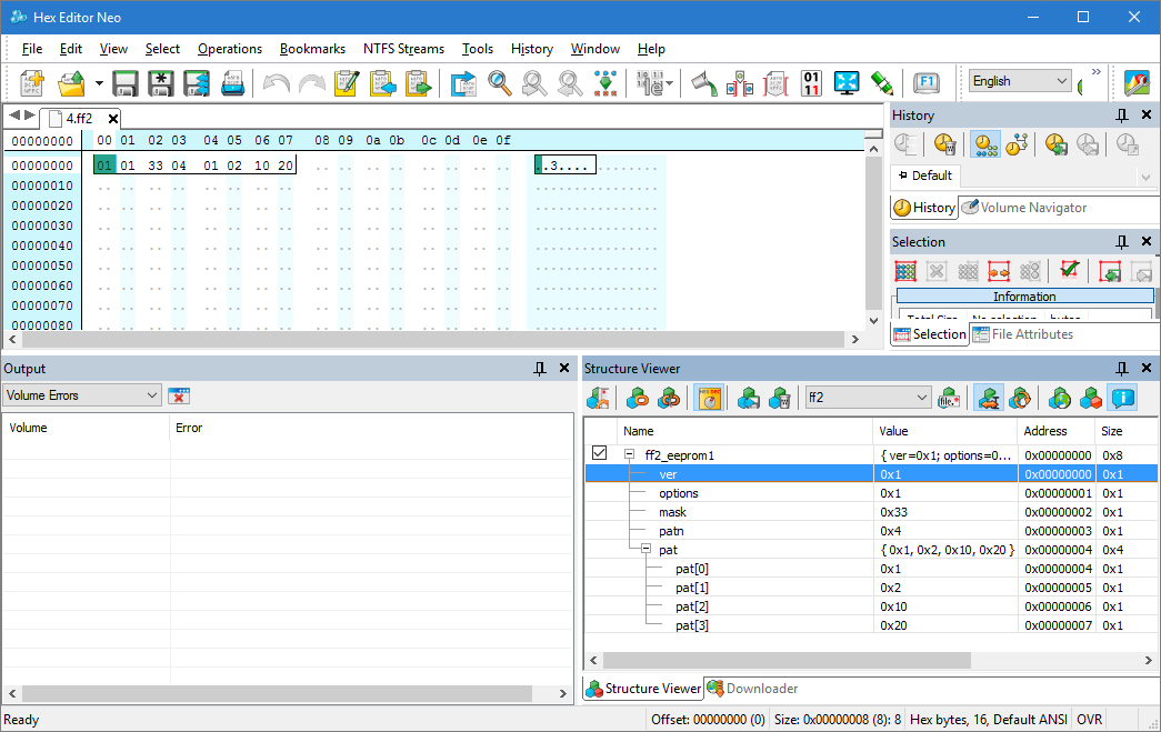
Above is a hex dump of the EEPROM with structure. The four LEDs are flashed on one at a time. In the current implementation, each flash is 50ms, the next LED to flash is selected at random, the wait time between flashes is uniformly randomly distributed between 0s and 4s. The code is more flexible, but simple should be enough to scare foxes, possums, cats etc.
The LDR is on P3.2 (INT0). The port is configured as an input only port to reduce the hysteresis effects of the 8051 traditional quasi bidirectional pin multistage pull up. This also allows higher resistance LDR and bias resistor resulting in lower operating current.
The critical voltages on the LDR input pin are 1.4 and 1.6V (it is a Schmidt trigger input), for 4.0V supply and 100kΩ bias resistor, that is equivalent to resistance of 53Ωk and 65kΩ (the chip input circuit in INPUT ONLY mode has little influence on the voltage developed).

Above is the characteristic of the GL5549 LDR. The pink marks the critical resistance region, and it corresponds to around 30lx.
The code is written in 8051 assembler. Some considerable frustration was due to inadequate, plain wrong datasheets, and lack of support on STC microcontrollers… be wary of choosing them for an important project and be suspicious of any equipment that uses them. The ISP tool is necessary as it is a proprietary protocol, but it is unreliable, partially English language, partially Chinese.
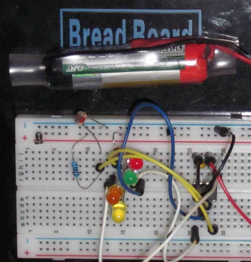
Above the prototype on a breadboard. The battery is in the top of the pic, microcontroller middle right on the breadboard.
Subject to the prototype trial, I will make a few of these to locate around the garden to discourage our digging friends. The final implementation might be a pair of green eyes and a pair of red eyes… scope for further experimentation.
Current is voltage sensitive, but at 4V, power down current is around 0.05mA and operating current is 1.0mA + LED current. For the configured cycle (50ms on, 2000ms off (avg)), average LED current is 10*50/2000=250µA. For 12 hours of daylight, total consumption during 24h is around 12*0.05+12*1.0=12.6mAh giving a battery endurance of 1200/12.6=95 days (ignoring self discharge). Battery capacity is reduced at temperatures below freezing. (If you have noted revision of these numbers, I have improved the code to reduce consumption, mainly through exploitation of the idle and power down facilities in this MCU.)
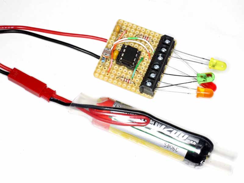
Above, the first prototype. This one has two resistors from Vcc to allow two sets of common anode LEDs switched by the four outputs. This allows correct current sharing for two LEDs per output phase (eg pair of eyes).