(Sevick 2001) discusses efficiency of transmission line transformers that use nickel-zinc ferrites in Chapter 11 “Materials and power ratings” applied to broad band baluns.
In Chapter 11 he reports a range of measurements of two different basic configurations, a 4:1 Ruthroff balun and a 4:1 autotransformer and uses nickel zinc ferrite cores of types that are no longer readily available (and none were the K and 52 mixes he is said to have recommended).
The types of transformers he built are ones where core flux (and so core loss) at low frequencies is approximately proportional to the quotient of voltage impressed across the input terminals and number of turns, so core losses can be decreased by reducing voltage and/or increasing turns. These are Voltage Baluns, see Definition: Current Balun, Voltage Balun.
By contrast, the flux (and so the core losses) in Current Baluns is proportional to the common mode current times turns, and in antenna systems, that cannot be simply calculated using back of the envelope ohms law (though pundits often do it), see Baluns – Rule 500.
So Seviks experiments and discussion are not directly applicable to Current Baluns, yet they are cited by manufacturers, sellers, and users as rationale for their designs using nickel-zinc ferrites for Current Baluns.
This is not to say that the choice might not be appropriate for some applications, but Sevick’s analysis does not provide compelling evidence to overlook manganese-zinc ferrite which is not only cheaper, but may deliver a better balun, one that reduces common mode current more effectively and reduces that current sufficiently that the Icm^2*Rcm product is lower than for a practical nickel-zinc ferrite core.
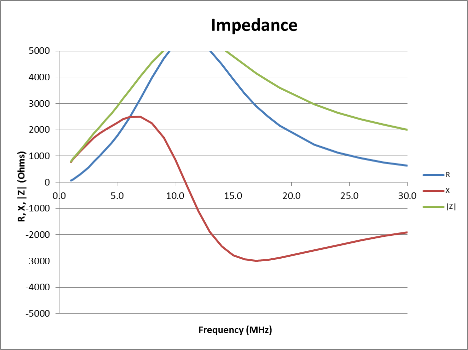
Following are models of Guanella 1:1 current balun choking impedance using three cores of two different core types.
FT240-52 11t nickel-zinc µi=250
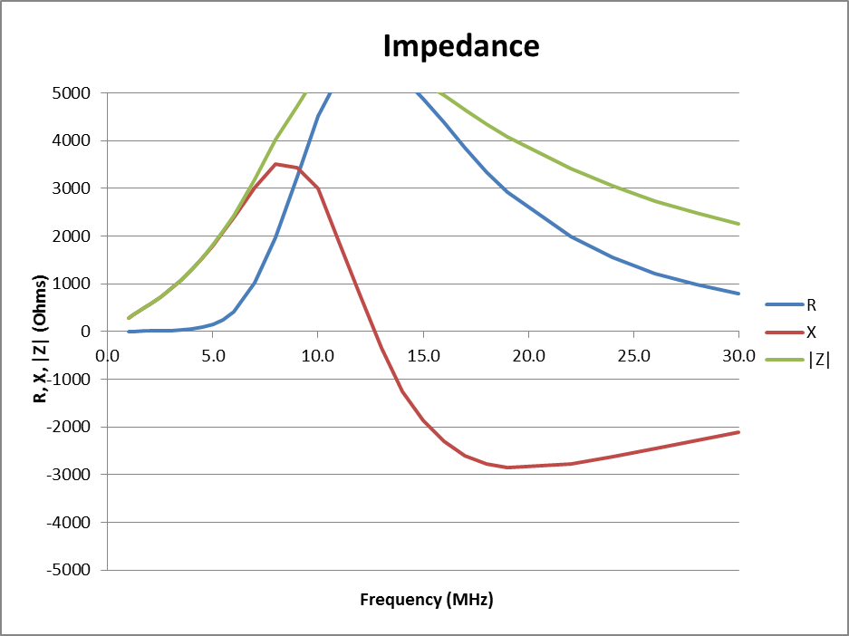
FT240-43 11t nickel zinc µi=800
FT240-61 15t nickel zinc µi=125

Comparison
At the high frequency end, there isn’t much to choose from the first two, they are fairly similar. At the low frequency end, the #43 balun has higher choking impedance and that would suggest it is likely to be more effective in reducing common mode current but you need to know Icm^2 in the specific scenario to calculate core losses.
It is true that the R term of Z for the #52 mix is lower at 3.6MHz than #43, and that will tend to give lower losses, you need to know Icm^2 in the specific scenario (which will probably be higher) to find the core losses.
The curves for #61 show that its Rcm is lower, but even with 15t, its choking impedance is low and narrower band than the others and whilst some would regard the core material’s lower loss a feature, it is less suited to a broadband HF balun application.
References
- Sevick, J. 2001. Transmission line transformers 4th Ed. Noble Publishing Co.