Lets use a simple test circuit to review the meaning of some oft misused terms associated with VNA and antenna analyser measurements.
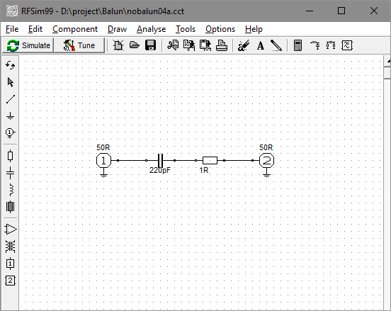
Above, the test circuit is a nominally 220pF COG capacitor connected between tx and rx ports of a two port VNA. An extra 1Ω series resistance is included to model the likely effect of capacitor ESR.
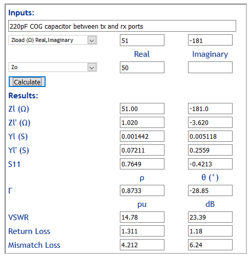
Above is a calculation of several related results seen from the input port at 4MHz (and based on the nominal circuit).
The important ones we will discuss are:
- ReturnLoss=1.18dB; and
- MismatchLoss=6.24dB.
Note that these figures are sometimes given as negative values by people / software contrary to industry standard meanings, the signs above are correct. Some software plots ReturnLoss with +ve values that increase downwards which is quite unconventional… Westerners usually plot Y increasing upwards and X increasing to the right.
These are easily calculated using quite well known formulae, and the internals of the calculator referenced above are visible in a browser using “view page source”.
The ReturnLoss tells us that Pref=Pfwd/10^(1.18/10)=76.21%Pfwd, and MismatchLoss tells us that power into the network Pin=Pfwd-Pref=Pfwd/10^(6.24/10)=23.77%Pfwd.

Above are the S parameter results of simulation of the network. S parameters are the most common metrics used with VNAs (but some ham software shields users from S parameters, often mislabeling what were S parameter results).
S parameters are complex quantities (having both real and imaginary parts), and the notation in this article |Sxx|=ydB is short hand for 20*log(|Sx|)=ydB, it does not violate the meaning of ||.
At 4MHz, |S11| is -1.17dB and since ReturnLoss(dB)=-|S11|(dB), it reconciles with the previously calculated ReturnLoss. We can calculate MismatchLoss=10*log(1-10^(-1.17/10)=6.268dB
|S21| is -6.34dB. S21 is the ratio of Vfwd at the output port to Vfwd at the input port. In a 50Ω context, we can think of |S21| in dB as the ratio of Pfwd at the output port to Pfwd at the input port expressed in dB. in dB both, InsertionLoss is equal to -|S21|.
We can calculate the network’s Loss (or TransmissionLoss) as 10*log(Pin/Pout), and in dB, Pin-Pout. Since Pin=Pfwd-MismatchLoss and Pout=Pfwd+|S21|, we can write Pin-Pout=(Pfwd-MismatchLoss)-(Pfwd+|S21|)=-|S21|-MismatchLoss=–6.34-6.27=0.07dB.
A COG capacitor is moderately low loss, and we should expect near zero network Loss (or TransmissionLoss) so our result is in line with expectation.
If you perform this test and your software tells you TransmissionLoss is more like the |S21| figure calculated, you know the software is defective. Some ham grade VNAs incorrectly label |S21| as TransmissionLoss.
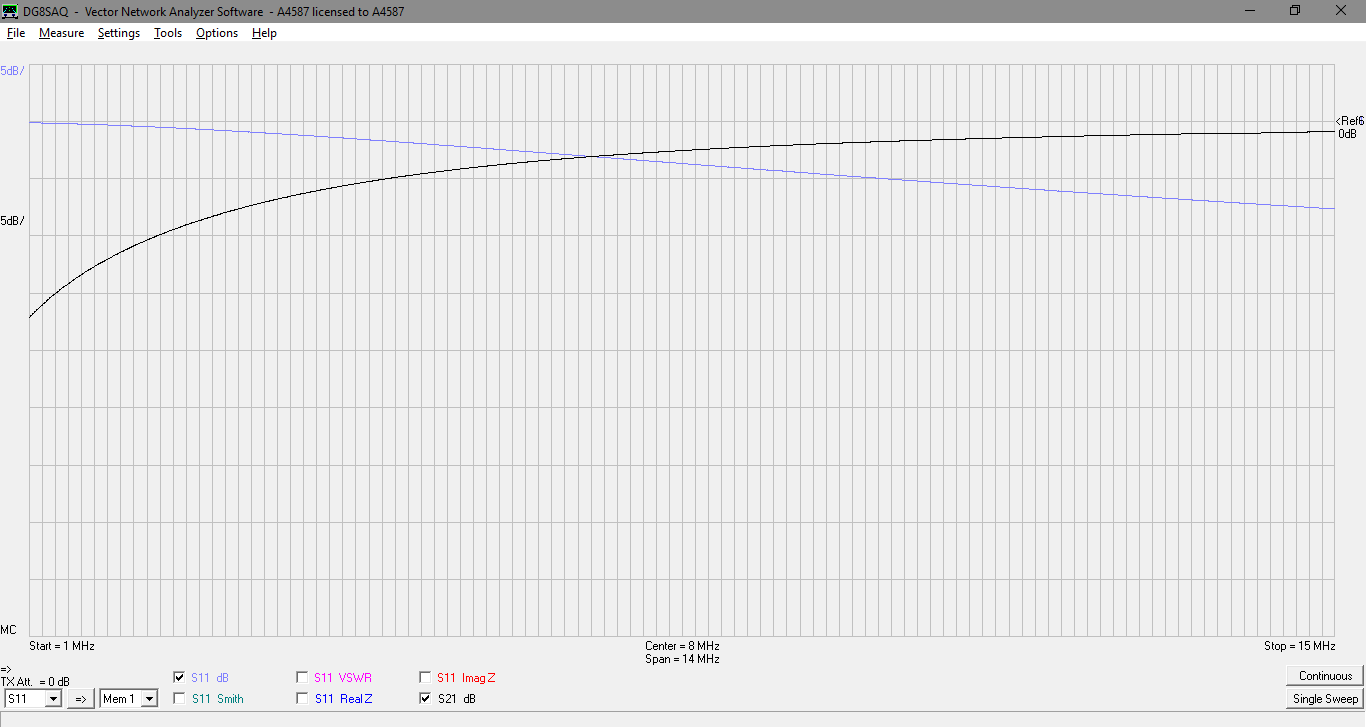
Above is a VNA sweep of a the real capacitor, a measurement from 1 to 15MHz showing |S11| and |S11|.
One could calculate MismatchLoss from the plotted |S11| and compare it to -|S21|, they should be very close for a low loss network such as this. (Ideally measured -|S21| would be greater than measured / calculated MismatchLoss, but they should be so close that measurement error may well result in the opposite. The key finding should be that they are almost the same, and of course that measurement uncertainty means this is not a good way of measuring the loss of a grossly mismatched low loss network.
Conclusions
Ham grade VNAs and analysers are often accompanied by software which has defects and the systems should be validated before relying upon them.
A simple test to validate measurement, calculations and display for a two port VNA is to connect a low loss reactance between the tx and rx ports, and evaluate the measured results against expectations.