KL7AJ proposed a little test for his readers on QRZ:
One of the most useful (and sometimes astonishing) principles in radio is the Conjugate Match theorem. In the simplest terms, what this says is that the maximum power will be transferred between a source (like a transmitter) and a load (like an antenna), when the source impedance is the COMPLEX CONJUGATE of the load impedance (or vice versa).
Here’s a neat little experiment to prove the conjugate match theorem. You need four basic ingredients: an antenna analyzer like the MFJ259 (or an actual impedance bridge, if you know how to use one). A good low loss antenna tuner. A good 50 ohm resistor. And a good 200 ohm resistor. And some appropriate connecting hardware, namely some short bits of coax.Step 1) connect the 50 ohm resistor to the OUTPUT of the antenna tuner. Connect the antenna analyzer to the INPUT of the antenna tuner.
Step 2) Adjust the antenna tuner to get precisely 50 ohms, zero reactance on the antenna analyzer. This step simply confirms everything is working.
Step 3) Replace the 50 ohm resistor with the 200 ohm resistor. Readjust the antenna tuner to get 50 ohms, zero reactance on the antenna analyzer. Do not disturb the antenna tuner adjustments after this point.
Step 4) Remove the 200 ohm resistor and insert the antenna analyzer in its place (at the OUTPUT of the antenna tuner).
Step 5) Insert the 50 ohm resistor at the INPUT of the antenna tuner.
Step 6) Take a careful reading of the antenna analyzer. (What do you think it will say?)
10 points for anyone who will correctly explain why this works.
Some clarifications
Jacobi maximum power transfer theorem
Jacobi published his maximum power transfer theorem in 1840. It states that maximum power is transferred from a (Thevenin) source to a load when the load resistance is equal to the (Thevenin equivalent) source resistance.
It was later adapted to apply to AC circuits with sinusoidal excitation, maximum power is transferred from a (Thevenin) source to a load when the load impedance is the complex conjugate of the (Thevenin equivalent) source impedance.
Walt Maxwell’s Conjugate Mirror
(Maxwell 2001 24.5) states
To expand on this definition, conjugate match means that if in one direction from a junction the impedance has the dimensions R + jX, then in the opposite direction the impedance will have the dimensions R − jX. Further paraphrasing of the theorem, when a conjugate match is accomplished at any of the junctions in the system, any reactance appearing at any junction is canceled by an equal and opposite reactance, which also includes any reactance appearing in the load, such as a non-resonant antenna. This reactance cancellation results in a net system reactance of zero, establishing resonance in the entire system. In this resonant condition the source delivers its maximum available power to the load. …(1)
Note that it states that if a conjugate match is established an any junction, then a conjugate match occurs in any (all) other junctions, simultaneously a conjugate match exists everywhere.
Analysis of KL7AJ’s experiment
KL7AJ’s experiment never actually directly measures power transfer, much less that it is maximised.
What it does do is create a conjugate match for a 50+j0Ω source at the input looking from transmitter port to output load on antenna port in Step 2, then attempt to show in Step 6 that when the instrument looks back from the antenna port to the matched load at the input, that measured impedance is the complex conjugate of the original output load. This is actually testing Walt Maxwell’s Conjugate Mirror proposition.
A similar experiment
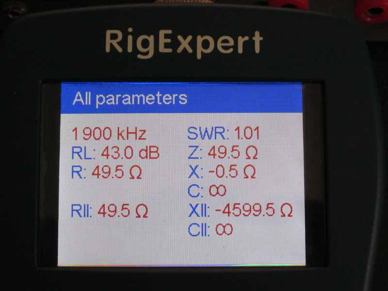
I am going to perform a very similar experiment which will test the stated “Conjugate Mirror Proposition”. The experiment is at 1900kHz to minimise the effect of adapters and load resistor imperfections and uses the ubiquitous MFJ-949E ATU. Measurements are made with a Rigexpert AA-600 which demonstrates good accuracy on a known 50Ω load.
- Measure a nominal 10Ω resistor

Above, the nominal 10Ω reads 10.1+j0.2Ω, this is the critcal value that will be tested later.
2. Adjust the ATU for a perfect match for 50Ω using the AA-600 connected to its input (TRANSMITTER) and the 10.1+j0.2Ω on the output (COAX1).
Above, ATU adjusted for near perfect match (better than the inherent accuracy of the instrument) with the 10.1+j0.2Ω output load.
3. Without changing the ATU controls, connect a 50+j0Ω load to the input port (TRANSMITTER) and measure the impedance looking into the output port using the AA-600 (COAX1).
Under the Conjugate Mirror Proposition, the measured impedance should be the complex conjugate of the original load resistor, 10.1-j0.2Ω.

Above, measured input impedance is 18.0-j0.8Ω.
It is quite different to the value predicted by the Conjugate Mirror Proposition, 10.1-j0.2Ω.
The experiment does not give the outcome that disciples of Walt Maxwell’s Conjugate Mirror Proposition would expect, it does not support the proposition and therefore questions its validity.
Should we have expected this outcome? Watch for a follow up post.
References
- Maxwell, Walter M. 2001. Reflections II. Sacramento: Worldradio books.