| OwenDuffy.net |
|
This article explores the challenge of coupling a transmitter to an electrically short unloaded mobile whip as might be used as a verstatile multiband HF antenna using an automatic ATU such as the SGC230.
The impedance at the base of an electrically short unloaded whip is a low value of resistance and high capacitive reactance. The shorter the whip, the lower the resistance and higher the capacitive reactance.
|
|
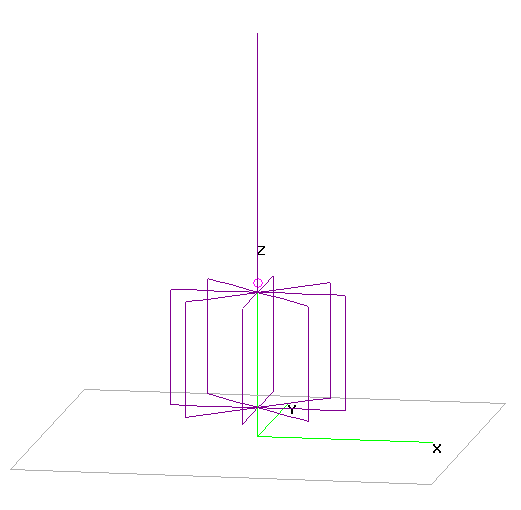
To explore the effects in a practical configuration, this analysis uses
an NEC model of a 2.6m vertical mounted on a wire frame drum of
diameter 2m, height 1.2m, and mounted 0.3m above average ground.
Assuming perfect conductors, the base feed impedance of this structure
at 3.5MHz is approximately 5-j2000Ω.
Note that feed point voltage is extreme for this configuration, at
100W delivered at the feedpoint, feedpoint current is 4.5A RMS, and
feedpoint voltage is 12.6kVpk.
Practical ATUs designed for this type of antenna have a very wide matching range, but are limited and will not match very short whips at lower frequencies. Beyond obtaining a match (input VSWR approximately unity), efficiently matching loads like this is a challenge for ATUs, and the lower the resistance component, the greater the challenge. The common designs are L or π-L networks.
Common commercial T-match tuners are not usually suited to the task
for several reasons.
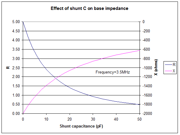 |
Shunt capacitance at the feedpoint alters the feedpoint impedance. Fig 1 shows that small shunt capacitance results in reduced resistance and reduced capacitive reactance.
The reduction in capacitive reactance is fine, but the lower resistance is more challenging for the ATU, and if it can match it, it does so with even lower efficiency.
 |
Whilst it is easy to visualise stray capacitance within a base
insulator assembly, proximity of the lower part of the antenna
structure or the connection from the ATU to whip has similar
effects.
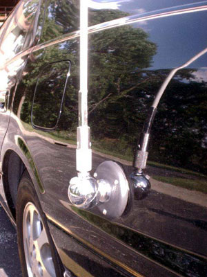
SGC in their article SG-237
on Toyota Camry show an unloaded whip on a Hustler split ball
base mounted on the side panel of Camry wagon, with an SGC ATU inside
the panel, see Fig 3. The proximity of the lower part of the whip and
the ball mount structure itself is likely to drive degraded ATU
efficiency on the lowest freqeuncies.
Stray capacitance at the antenna base of an electrically short unloaded whipe reduces feedpoint resistance and degrades ATU efficiency.
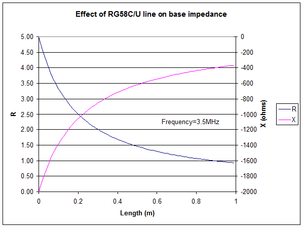 |
Coaxial cable between the ATU and antenna base results in impedance transformation. Fig 4 shows the impedance transformation for a range of lengths of RG58C/U. Again, resistance is decreases and capacitve reactance decreases.
The reduction in capacitive reactance is fine, but the lower resistance is more challenging for the ATU, and if it can match it, it does so with even lower efficiency.
The results will be similar for any 50Ω coax, and values for specific scenarios can be calculated using TLLC.
Coax should not be used between the ATU and an electrically short unloaded whip.
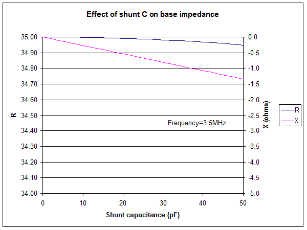 |
Fig 5 shows the effect of shunt capacitance on the base of a resonated loaded whip with feedpoint impedance of 35+j0Ω. Note the expanded R scale, the effect is insignificant.
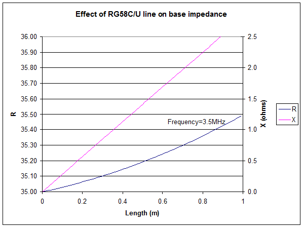 |
Fig 6 shows the effect of a length RG58C/U on the base of a resonated loaded whip with feedpoint impedance of 35+j0Ω. Note the expanded R scale, the effect is insignificant.
Whilst capacitance at the base does
not significantly effect a resonated loaded whip, the regions of the
whip above the loading coil are best kept clear of bodywork, especially
on base loaded and 'screwdriver' type antennas.
© Copyright: Owen Duffy 1995, 2021. All rights reserved. Disclaimer.