 |
| OwenDuffy.net |
|
A common task in setting up matching schemes for antennas is the adjustment of a shunt matching scheme, meaning some type of matching scheme where a load impedance at some point is adjusted for a parallel equivalent of 50 in shunt with some reactance which is 'tuned out' with a shunt reactive element of the opposite sign. These techniques work for a load impedance where the R component is lower than the desired matched value.
Common forms of such a match are an L match with the shunt element on the source side, and a single stub tuner.
This article offers a way of adjusting such a matching scheme using one of the ubiquitous analysers which lack direct admittance reading. The article does not explain how the match works or how to design it, but how to adjust implementation of a feasible design.
|
Fig 1 shows a single stub tuner on a 5/8λ vertical (Carr 2001). (Straw 2007, p26.12-15) explains the technique.
To match a 50Ω main feed line The length L1 is adjusted to obtain an admittance (Y) looking into L1 with the stub disconnected, of 1/50+jB (which is another way of saying 50Ω in parallel with some reactance -1/B).
Unfortunately, most low end antenna analysers do not directly display admittance or a parallel equivalent circuit.
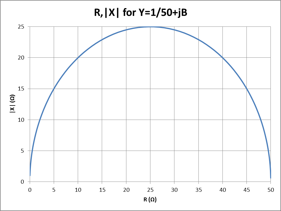 |
Fig 2 provides help in finding the values R,X which correspond to Y=1/50+jB. The graph shows all the combinations or R and X that result in a parallel equivalent of 50Ω in parallel with some reactance.
To use this chart with the single stub match, the length L1 would be adjusted repeatedly for an R,X pair that falls on the blue line in Fig 2, eg 3,12.
The shunt stub can then be attached and adjusted in length for minimum VSWR (which should be very close to 1). Loss in the stub means that a R,X pair lying slightly above the blue line is needed to offset the loss introduced by the stub.
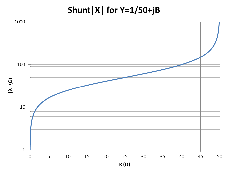 |
Fig 3 shows the magnitude of the shunt reactance needed to offset the reactance of an admittance Y=1/50+jB given the equivalent series R of that admittance. The sign of the reactance will be the opposite to the sign of X in Z.
So, for the example case, R=3 and from Fig 3, the required shunt reactance to tune the match will be about 12Ω, which in Fig 1 is supplied by the s/c stub.
If the VSWR on line section L1 can be read reasonably accurately, there is a quicker way to the solution.
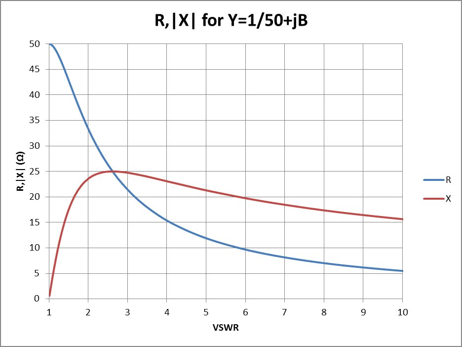 |
Fig 4 shows R,X combinations for Y=1/50+jB given VSWR on line section L1.
So, if the VSWR on the L1 was say 6, then the combination of R,X for Y=1/50+jB is approximately 10,20 so L1 would be adjusted repeatedly for 10,20.
Again, the shunt stub can then be attached and adjusted in length for minimum VSWR (which should be very close to 1). Loss in the stub means that a R,X pair with slightly higher X is needed to offset the loss introduced by the stub.
Lets take an M40a 40m helically loaded mobile whip as an example.
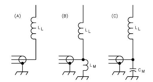 |
(Straw 2007, p16.14) describes the technique for shunt matching a loaded mobile whip. Fig 5 is Fig 20 from the reference, showing the possible configurations.
A common matching scheme is to shorten the whip to obtain a feed point admittance Y=1/50+jB, and to use a shunt inductor to 'tune out' the parallel reactance -1/B, (B) in Fig 5. (This is in effect a L match where the series element is supplied by the shortened antenna.)
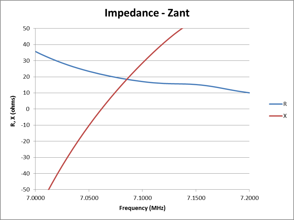 |
Fig 6 shows measured R,X at the feed point (without the shunt inductor) across the band.
This whip can be matched to 50Ω line by adjusting its length so that an R,X pair that falls on the blue curve of Fig 2 is at the desired operating frequency. In this example, the objective is centre the whip at the top of the CW segment so that it spans the low end of the phone segment and the CW segment (7.000 to 7.040MHz in VK), so the length has been adjusted to get such a pair close to 7.040MHz.
It can be seen that at 7.035MHz, Z=26-j25 which is an R,X pair that falls on the blue curve of Fig 2. A shunt coil can be connected and adjusted for minimum VSWR at 7.035MHz (and it will be very close to 1). From Fig 3, the required coil reactance for R=26 is about 50Ω, about 1.1µH inductance at 7MHz.
Figs 2, 3 and 4 in PDF format for field reference
| Version | Date | Description |
| 1.01 | 07/06/2012 | Initial. |
| 1.02 | ||
| 1.03 | ||
| 1.04 | ||
| 1.05 |
© Copyright: Owen Duffy 1995, 2021. All rights reserved. Disclaimer.