 |
| OwenDuffy.net |
|
| This article compares a model based on the technique in Bootstrap coax traps for antennas with measurement of a prototype trap. |
Karl-Otto Muller (DG1MFT) constructed a bootstrap coax trap and made a series of measurements using a Rohde & Schwarz ZVRE Vector Network Analyser.
|
Fig 1 shows the trap under test.
 |
Fig 2 shows the physical details of the coax trap from photographs and measurements supplied by Karl-Otto.
 |
Fig 3 shows the results of the inductance calculator for the inductor formed by the outer surface of the outer conductor of the coaxial cable coil from sheild to shield before it is connected in the trap configuration. The calculated self resonance does not apply to the trap configuration.
The length of Belden 8262 (RG58C/U) coax used in the model was the mean wire length of 1.42m plus 0.15m for the end connections in the actual trap construction.
A parallel stray capacitance of 5pF was used to better reflect the fact that the coax is jacketed with PVC dielectric, and an allowance of capacitance of the end connections in the test jig.
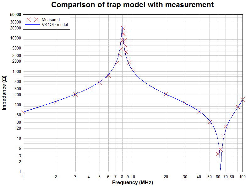 |
Fig 4 is a plot of the calculated values and the measured values.
There is a slight offset in resonance of about 240kHz probably caused by the accuracy of the inductance estimate and the accuracy of the estimate of the coax length. A model based on the measured inductance (2.36μH) eliminated most of this error.
The Q of the inductor was adjusted to calibrate the model to the measured impedances. The model uses Q=18 at 1MHz, and Q∝f^0.5. This is much lower Q that would be expected from a coil of solid copper wire of the same diameter as the coil of coax. The suggestion is that the braided conductor has relatively high effective RF resistance.
Informed designers usually avoid operation of the trap at resonance, so it is the accuracy of the impedance components at frequencies away from resonance that is of most interest in designing and modelling antennas based on this type of trap.
Bootstrap coax traps for antennas
A trapped dipole for 80m and 40m using bootstrap coax traps
| Version | Date | Description |
| 1.01 | 30/09/2007 | Initial |
| 1.02 | ||
| 1.03 | ||
| 1.04 | ||
| 1.05 |
© Copyright: Owen Duffy 1995, 2021. All rights reserved. Disclaimer.