| OwenDuffy.net |
|

The W5GI Mystery Antenna is described by its designer as A multi-band wire
antenna that performs exceptionally well even though it confounds antenna
modeling software
(Basilotto 2004).
Notwithstanding that, this article is a quantitative analysis of the W5GI Mystery Antenna in an inverted V configuration using an NEC model of a typical installation.
W5GI's Mystery Antenna is available for direct purchase, his website
(Basilotto 2004)
contains the offer W5GI will build an antenna for a nominal fee.
Discount prices
start at $65.00, plus shipping, for the W5Gi multi-bander. Mono band
antennas cost more because a 4:1 balun is used.
W5GI acknowledges an article by W2OZH as inspiration for the W5GI Mystery
Antenna, and describes it The W5GI
Multi-band Mystery Antenna is a fundamentally a collinear antenna
comprising three half waves in-phase on 20 meters
with a half-wave 20 meter line transformer
. He goes on to claim that
the antenna covers 80 to 6 meters with low feed point impedance and will work
with most radios, with or without an antenna tuner
.
The antenna is a centre fed dipole of length 15.1m a side,
with the middle third of each leg comprising a section of
RG8X coax connected as a s/c stub that is electrically inserted at one
third of the length from the centre. It is fed
by a matching section
of 300 ohm feed line that is an electrical half
wave at 14.2MHz, then an arbitrary length of 50
ohm coax to the ATU / transceiver. The model used for this article uses
sufficient RG213 coax to make a total of 25m of
feed line to model feedline losses in a realistic installation.
The stub and the feed line elements are modelled using the techniques described at RF Transmission Line Loss Calculator. Analysis is based on calculation of the stub impedance, then the feed point impedance from an NEC model of the dipole, computed every 0.1MHz from 1MHz to 30MHz. The real performance of transmission line elements in terms of impedance transformation and loss, and a practical L-match tuner network components and loss are calculated to form a view of the overall losses in the feed arrangement from transmitter to dipole centre.
Table 1 sets out the design parameters that are common to all of the configurations modelled in this article.
| Item | Value |
| Design frequency | 14.2MHz |
| Height of centre | 10.0m |
| Height of ends | 10.0m |
| Length of half dipole | 15.1m |
| Included angle | 180° |
| Antenna conductor | 2mm diameter copper |
| Ground | "real" ground (σ=0.005S, ε=13) |
| Matching section line type | 300 ohm open wire (1mm/8mm) |
| Length of "matching" section | 9.64m |
| Length of coax feed line | 15.4m |
Table 2 sets out assumptions underlying the models.
| Assumptions |
| Antenna is erected over "real" ground (σ=0.005S, ε=13). |
| Ideal balun is used, and that common mode feedline current is insignificant. |
| L-match tuner used to transform load to 50+j0 Ω to suit a transmitter. |
| Total transmission line from antenna centre to transmitter is 25m. |
The results given here, and the associated discussion are of the model as described. Different models, and in particular, real implementations will be different to some extent.
Note that this model does not pretend to model exactly W5GI's
implementation, his article does not detail the height of the dipole.
The length of coax used or required is not quite clear at one point in
the article, he states
he used 34' of RG8X coax, though if the antenna is designed to have low
VSWR(50), the length of coax should not be critical. Though he
gives a table of VSWR and impedances, the impedances are highly
dependent on the length of coax feed line and therefore of limited
value if other lengths or types of coax are used. The model is also
senstive to variables like
ground parameters, the built environment, vegetation etc. Rather, the
model used here gives an expectation of what might be expected
in a typical application, and serves as a framework to review some of
the performance claims.
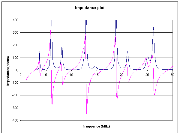 |
Figure 1 is a plot of the R and X values at input to 15.4m of RG213 feed line against frequency. The plot is cropped to show only the low R and X ranges, values off the plot will have unacceptable losses with practical lengths of coax line. The impedance seen by an ATU or transceiver is of course dependent on the length of coax used.
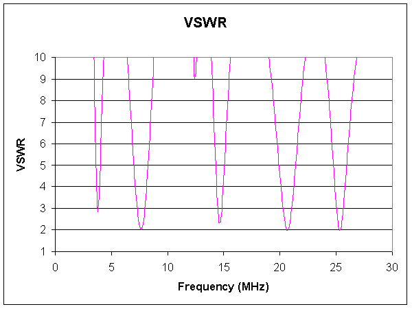 |
Figure 2 is a plot of the VSWR on the coax at the base of the matching section. The plot is cropped to show VSWR<10, values off the plot will have unacceptable losses with practical lengths of coax line. Longer coax sections or lossier coax will reduce the VSWR.
This VSWR results from the model do not support the designer's claim that the "antenna covers 80 to 6 meters with low feed point impedance and will work with most radios, with or without an antenna tuner" whatever "work" actually means. In this case, VSWR is below 2:1 in only two regions, but none of them are inside an amateur band. It may be possible with a little tuning to get less than 2:1 in part of the 15m and 12m bands.
The input impedances provided by the model suggest that not only will this antenna require an ATU on ALL HF bands, but it is probably beyond the limited range of many internal ATUs and a wider range external ATU will be necessary to comply with the load specification of most modern transceivers.
In a side note to the 20m impedance figures in his web article, W5GI
says "A electrical quarter wavelength of 75 ohm cable will reduce SWR
to 1:1 and will not have any affect on other bands". It is not clear
where this line section would be deployed, but in the absence of
specific instructions, I assume that it goes in front of the antenna
system as described, ie between ATU and 50 ohm coax section.
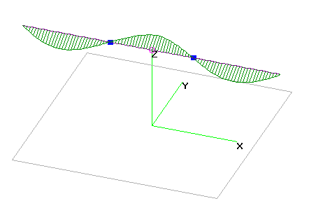
W5GI claims that the antenna is three half waves in-phase on 20m.
 |
The currents calculated in the NEC model do not support the claim that the three half waves are in phase on 20m, see Figure 3.
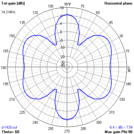 |
Figure 4 shows the model azimuth radiation pattern at 30° elevation at 14.2MHz with six lobes, characteristic of three half waves out of phase.
The pattern does not show the dominant broadside lobe in the +Y/-Y directions that would be expected from three half waves in phase. The antenna delivers maximum gain at 30° elevation, at which the four broader minor lobes are only 1.5dB less gain than the two narrow broadside lobes.
The designer claims a 3-6dB gain over a dipole and a six-lobe
radiation pattern with an elongated figure-8 pattern perpendicular to
the plane of the antenna
, though he gives no evidence to
support this. Two key points emerge:
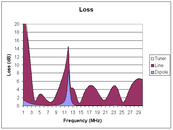 |
Figure 5 shows antenna system loss from the model. Loss in the copper conductor forming the dipole, and losses within the coaxial stubs are included in the "Dipole" category. The "Line" category includes loss in the 300 ohm matching section, and the 15.4m RG213 to the ATU. "Tuner" losses are for a practical L match. The L match used for tuner loss is in general, the most efficient way to transform the load impedance. Using the loss of a practical L-match tends to underestimate the loss in any other tuner configuration.
Note the large peak in "Dipole" loss at 12.3MHz. This coincides with the quarter wave resonance of the stubs, at which point they offer a very high resistive component that converts a large part of the RF power to heat. Not a big issue since there is not amateur band within the main peak, but it shows that transmission line elements aren't lossless, and they demand careful design consideration. The stubs do not provide very much inductive loading on the lowest frequencies, do not provide the phase reversal claimed and in-phase pattern, eat power, offer more wind resistance, and are probably weaker than practical HDC antenna wire, the antenna is probably better without them.
Most of the "Line" loss is due to loss in the RG213 feed line. Use of lossier grades would exacerbate the problem. Eliminating coax operating at high VSWR will improve efficiency of the antenna system.
The loss curve has some narrow sweet spots that coincide roughly with many of the lower HF bands, the challenge with a real antenna is whether those sweet spots are in the relevant bands, or adjustment so that they are so.
A model of a classic cophased three half waves collinear using wire phasing sections was constructed at 15MHz a height of 10m over average ground.
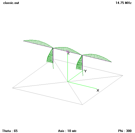 |
Figure 6 shows the structure and current distribution. The feed point impedance at resonance is 265+j0Ω. The high feedpoint R is due to high radiation resistance, due in turn to the high current moment of the three half waves in phase.
W5GI reports measured impedance for his antenna and VSWR, though he does not give the height of the antenna, or length of coaxial feed line to the measurement point.
Nevertheless, the impedance seen at the source end of his half wave of 300 ohm line should be in the range of 250Ω to 350Ω, which would cause VSWR of 5 to 7 at the load end of the coax, a little lower at the source end.
W5GI's measured VSWR=1.5 at 14.2 (where he claims three half waves in phase) is inconsistent with the higher impedance expected of in-phase operation. Note that W5GI does not use a balun on his multiband Mystery Antenna, so common mode feed line current will somewhat modify feed point impedances.
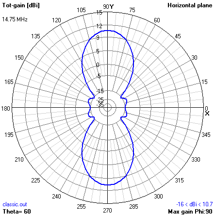 |
Figure 7 shows the radiation patter at maximum gain for the classic model. This is clearly a two lobed broadside pattern, and is the pattern expected of three half waves in phase, the minor lobes are more than 20dB down on the two major lobes.
The coax stub sections:
The stubs could be replaced with plain conductors without degrading the antenna overall.
What you then have is essentially, a G5RV. For further information, see:
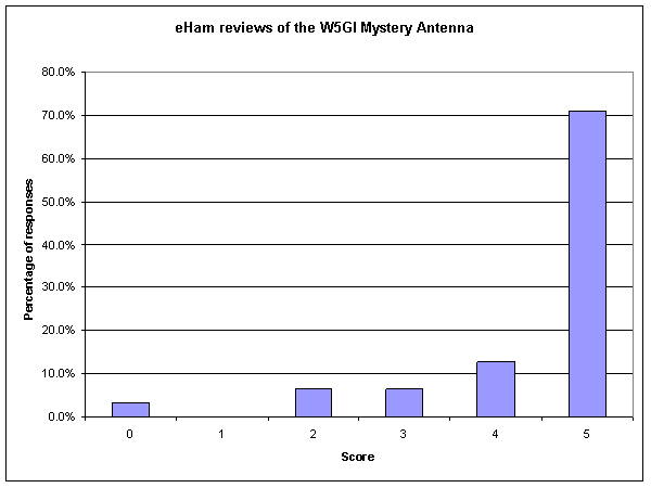 |
Figure 8 shows a summary of 31 eHam reviews of the W5GI Mystery Antenna at 14/07/2009 (Eham). The average score is 4.4, so most users seem very happy with it, even though it works quite differently to the designer's representations. That might speak more of modern ham's quiet acceptance of the designer's claims and the commercialisation of antennas than objective assessment, and possibly of the reliability of eHam reviews.
Update 25/10/2013: The eHam reviews link has only 14 reviews at this date whereas there were 31 entries at 14/07/2009 summarised above. at this time of the 14 reviews, 13 are 5/5 which is way better than 2009. It does look like there is something dodgy with eHam reviews disappearing resulting in a better overall review, confirming suspicions of the reliability of eHam reviews!
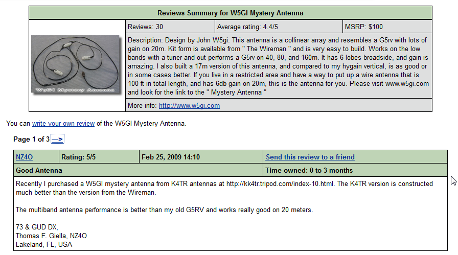 |
Figure 9 is a screen shot of the reviews in early 2009.
(Dube nd) claims It is the ONLY "W5GI Mystery Antenna" that is registered
with the United States Patent and Trademark Office Registration Number 3,805,488
.
A US patent search on 19/09/11 returns an entry for patent 3,805,488 issued in
1974 for a "capper chuck device", nothing to do with the W5GI Mystery Antenna...
more mystery! Searches for ttl/"Mystery Antenna", in/Basilotto, and an/Basilotto
returned no hits. A search for trade mark registration does turn up registration
of W5GI MYSTERY ANTENNA
to Dube in 2009.
The analysis is based on an NEC model of the radiator, using 4NEC2. A PERL script was written to calculate the stub impedance at frequencies from 1MHz to 30MHz in 0.1MHz steps, and to construct and run NEC models. Another PERL script parsed the NEC output and summarised the data as input to a spreadsheet for presentation development.
Transmission line parameters come from the Transmission Line Loss Calculator and Two Wire Transmission Line Loss Calculator.
(Note that none of the results depend on approximations based on VSWR, in fact VSWR is calculated during the analysis for presentation, but not used as an intermediate value... ie nothing is calculated from VSWR.)
| Version | Date | Description |
| 1.01 | 30/03/09 | Initial |
Use at your own risk, not warranted for any purpose. Do not depend on any results without independent verification.
© Copyright: Owen Duffy 1995, 2021. All rights reserved. Disclaimer.