 |
| OwenDuffy.net |
|
NEC2 and NEC4 support a GM card to translate and rotate a structure in three three dimensions.
This article gives a simple but practical example of exploitation of this often overlooked facility.
Most beginners to NEC start by modelling a centre fed half wave dipole as their first modelling project. It is a good start, as it can be modelled very simply with just a single wire element defined on a GW card.
The next adventure might well be to adapt that starting configuration to model a centre fed Inverted V half wave dipole. The immediate problem is that it is going to take at least two, and preferably three GW elements to model the sloping legs and possibly a short horizontal middle section for best symmetry. The challenge to many is defining the 3D coordinates for the dipole ends such that the legs have some given length (approximately equal to the leg lengths of the simpler centre fed Inverted V half wave dipole, and then to conveniently adjust the leg lengths to optimise the tuning of the dipole.
The GM card is very useful in meeting these challenges, and good approach to definition of the structure is to exploit symmetry and repetition of elements.
So, lets think of the Inverted V dipole as a pair of similar sloping legs attached to a short horizontal joining section which is where the source is attached.
Lets start by defining one of the sloping sections.
GW 1 8 0 0 0 10.15 0 0 0.001
This is a 2mm diameter wire of 8 segments from 0,0,0 to 0,0,10.15 (so it is of 10.15m length). This is the beginnings of the sloping legs which we will attach to a central horizontal section of 0.3m. The total linear length of the final structure will be twice this section length plus the centre section length or 2*10.15+0.3m. Changing this one instance of the value 10.15 will adjust both legs of the final dipole structure for tuning purposes, metre for metre.
So, lets move and rotate the above GW structure so that it slopes down at 30° to the horizontal axis (we will rotate it 30° about the Y axis), and move it so that the end at 0,0,0 connects to the proposed centre section.
GM 0 0 0 30 0 0.15 0 0 1
The above GM card achieves that objective of rotate and move without copying (creating any new structures). This card defines in just one figure the down slope of both legs in the final dipole structure.
Now lets create the other sloping leg by creating a copy of the structure rotated 180° about the Z axis.
GM 1 1 0 0 180 0 0 0 1
Now we need to define the short central section.
GW 3 1 -0.15 0 0 0.15 0 0 0.001
So, all three wire sections are defined and connected up, but the centre of the dipole is a zero height, so lets raise the whole structure by 11m in the Z axis direction.
GM 0 0 0 0 80 0 0 11 1
The single value 11 on this card defines the height above ground of the whole structure and can be used to adjust its height to explore the effect of changes on pattern, tuning, and feed point impedance.
Now the dipole has been defined oriented along the X axis. Lets say we want to relate the pattern plots to the lat/lon grid, and the dipole will actually be installed in a line 10° clockwise from true north. So, lets rotate the entire structure 80° about the Z axis to calibrate our azimuth pattern plot Y axis to true north.
GM 0 0 0 0 80 0 0 11 1
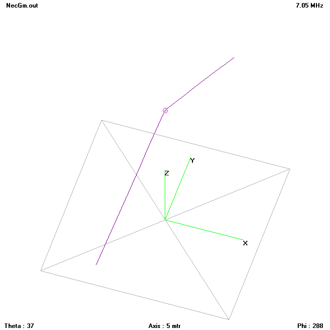
| |
Fig 1 above is a view from overhead of the final structure. It can be seen that the dipole is oriented just a little clockwise of the Y direction or north for our purposes.
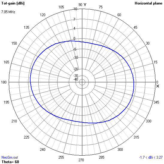 |
Fig 2 shows the azimuth pattern of the antenna oriented to Y as true north.
So, here is the final card deck.
CM Demonstration of GM card
CM Owen Duffy 2011 10 29
CE
GW 1 8 0 0 0 10.15 0 0 0.001
GM 0 0 0 30 0 0.15 0 0 1
GM 1 1 0 0 180
0 0 0 1
GW 3 1 -0.15 0 0 0.15 0 0 0.001
GM 0 0 0 0 80 0 0 11 1
GE 1
GN 2 0 0 0 13 0.005
EK
EX 0 3 1 0 1 0 0
FR 0 0 0 0 7.05 0
EN
The advantage of this approach is that the wire lengths are defined directly, the slope of the legs and the orientation are defined by single values, all of which makes adjustment of the model direct and convenient.
| Version | Date | Description |
| 1.01 | 14/11/2011 | Initial. |
| 1.02 | ||
| 1.03 |
© Copyright: Owen Duffy 1995, 2021. All rights reserved. Disclaimer.