 |
| OwenDuffy.net |
|
*** DRAFT ***
Valve data sheets are often short of interesting detail, they were largely produced decades ago when computer modelling tools were not widely used and they often are interesting guidelines rather than hard and fast rules which must be followed.
Hams are one of the continuing users of small to medium transmitting valves, and many modern hams take valve datasheets quite literally offering their counsel freely and frequently as online experts.
Lets firstly explore the limits stand alone, then bring them together in a big picture.
It is worth separating absolute maximums from recommended operating points, and testing the absolute maximums for consistency and credibility.
Some common key parameters are:
Cathode current is limited by different mechanisms for different cathode types. The most common cathodes used are indirectly heated coated cathodes and directly heated thoriated tungsten cathodes.
Excessive instantaneous cathode current in an indirectly heated coated cathode risks stripping of the cathode coating and it risks permanent damage to the valve.
Attempting to exceed the limit of cathode current in a directly heated thoriated tungsten cathode will result in temperature limited emission, the cathodes capacity to supply free electrons is saturated and non-linear operation occurs. Saturation of the cathode in this way does not cause permanent damage to the cathode.
In the absence of clear specification of maximum instantaneous cathode current, an estimate can be made from the recommended operating conditions.
More often than not, application recommendations do not specify maximum instantaneous cathode current, but do specify DC anode current (probably because it was so easy to measure, and most transmitters had DC anode current metering).
We can make a reasonable estimate the peak anode current from the DC anode current and conduction angle. For 120° conduction angle, Iapk is about 4.2 times Iadc and for 180° conduction angle, Iapk is about 3.1 times Iadc. If grid current is low, then cathode current will be similar and have similar factors.
Example
The Eimac 1980 datasheet for a 3-500Z does not specify maximum instantaneous cathode current, but it does specify:
So for AB2, the datasheet implies maximum instantaneous peak anode current to be 3.1*0.400=1.24A.
And for plate modulated Class C, the datasheet implies maximum instantaneous peak anode current at the peak of modulation cycle to be 4.2*2*0.275=2.3A.
Clearly the valve cathode must be able to supply 2.3A instantaneous current, so that implies that it should handle a maximum DC current in AB2 of up towards 2.3/3.1=0.74A.
The cathode is heated not only by the heater supply or filament supply, but the anode and grid current flows in the cathode and contributes to heating. Some valve datasheets specify a maximum RMS cathode current. Overheating the cathode by excessive RMS cathode current may shorten valve life. Whilst valve manufacturers do not usually give a time over which the RMS value is measured, the thermal latency involved suggests that averaging over several seconds is probably appropriate for SSB telephony operation.
The RMS value of cathode current is not simple to measure, and not simple to calculate, though factors can be derived for typical class conduction angles so long as peak grid current is small (not always the case with hard driven triodes).
This parameter is more likely to be specified for pulse operation, and more relevant to that mode. For valves where maximum RMS cathode current is not specified, it is usually safe to not consider the effect.
Maximum instantaneous anode to cathode voltage is sometimes stated directly and clearly, but more often voltage limits are stated indirectly within mode recommendations, which is interesting because it is a not-to-exceed value, not-to-exceed even for an instant as it risks flashover within the valve and potentially serious damage to the valve and its surrounding circuitry.
If the parameter is not specified, a good estimate can be made.
Keep in mind that in a Class A, B or C tuned RF amplifier, the instantaneous peak RF voltage is usually no higher than about twice the DC supply, a better estimate is the DC supply voltage plus the peak RF voltage which is approximately 2*Vs-Vakmin (twice the supply less the minimum anode voltage).
Recommendations for Class B (inc AB1, AB2) usually have rather conservative supply voltage parameters.
More interesting is the recommendation for plate modulated Class C operation. The effect of plate modulation is to effectively run the power amplifier from a much higher supply at peaks of the modulation envelope, so peak Vs can be taken as Vs*(1+m) where m is the modulation index. In the absense of other advice, m can be taken as 1, so peak Vs is twice the DC supply specified.
Combining the AM recommendation with knowledge of the instantaneous peak voltage, the not-to-exceed Vakmax equals Vsam*2*2-Vakmin.
Example:
The Eimac 1980 datasheet for a 3-500Z does not specify Vakmax, but it does specify:
If we examine the anode characteristics, Vakmin is somewhere in the range 300-500V, lets assume 400V.
So for AB2, the datasheet implies instantaneous anode voltage to be 2*4000-400=7600V.
And for plate modulated Class C, the datasheet implies instantaneous anode voltage to be 3000*2*2-400=11600V.
Clearly the valve must be able to withstand 11,600V, so that implies that it should withstand peaks from a supply of up to (11,600+400)/2=6000V in AB2. The stated 4000V seems inconsistent with AM recommendations where the instantaneous supply voltage delivered to the power amplifier under amplitude modulation will reach twice the DC supply voltage.
Maximum average anode dissipation is usually clearly and directly stated. More important is usually the seal temperatures though they are sometimes not clearly stated, and manufacturers advise on a maximum average anode dissipation that is safe with the specified cooling. Note the cooling condition, if cooling is inadequate, the valve's maximum average anode dissipation is reduced.
For example, buried in the narrative of the 3-500Z datasheet are maximum temperatures for the anode seal and base seals, and various maximum average anode dissipation for related cooling systems and air flows.
The anode can have rather high heat capacity, and in that case temperature responds quite slowly, much slower than most modulation types so it is a relatively long term average that usually applies.
The grid structure has very low heat capacity, it responds to power dissipated quite quickly, and temperature responds quite quickly. It is very important that the grid does not become hot enough to emit electrons, or to sag structurally. Maximum average grid dissipation is usually stated for power grid valves, or an indirect parameter, maximum rectified grid current is specified.
For example, the 3-500Z datasheet specifies maximum grid dissipation at 10W and recommends rectified grid current up to 120mA in AB2.
Driving power grid valves to high output often means driving the grid positive wrt cathode, and grid current flows. It is critically important that excessive grid current does not flow, and protection circuits to shut the power amplifier down in the event of excessive grid currents are often good value.
Grid current should be directly metered, the grid current is a key not-too-exceed parameter and the meter is most useful in adjusting anode tuning and loading.
Maximum seal temperatures may be specified. Cycling temperatures beyond the suggested limits risks damage to seals, loss of vacuum and shortened valve life.
Cooling requirements are often stated, and they are usually pre-conditions to stated anode dissipation. Adequate cooling, amongst other things, helps to keep seal temperatures in range.
Though the previous discussion has focused on individual limits, it is unlikely that a valve can operate at a point where every parameter is on the limit. For example, to operate at maximum voltage and maximum current will usually exceed rated maximum anode dissipation.
The design challenge is to find a combination of operating parameters that does not exceed real absolute maximums within tolerances and margins for supply voltage etc, that can be implemented with available components, and that delivers adequate IMD performance. Operating the valve within these constraints should allow normal expected life from the valve.
The following explores a popular commercial power amplifier using the 3-500Z valve, the Ameritron AL80B. The author has no inside knowledge of the original design, but rather the following is if you like, reverse engineering of the power amplifier.
|
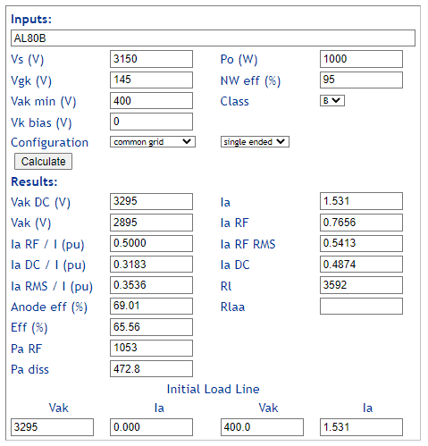
Fig 1 is an approximate load line calculation for a sample AL80B operating on a 240V 50Hz supply calculated using Calculate initial load line of valve RF amplifier. The model is based on reasonable assumptions for the operating conditions of the power amplifier at 1000W PEP SSB telephony output, and has been validated on test of a real AL80B amplifier under pulsed sine wave SSB that simulates telephony conditions and under real telephone operation.
Some key results from this simple model:
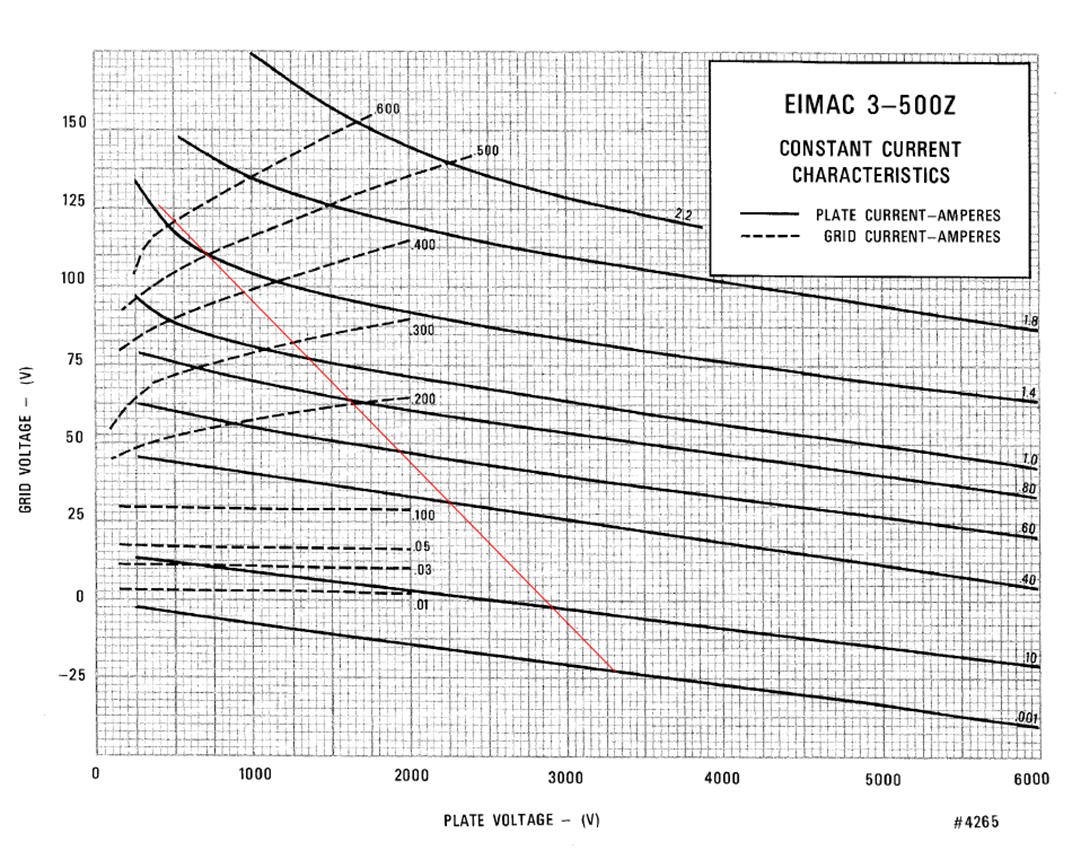 |
Fig 2 shows the initial load line calculated and shown in Fig 1 on the average anode characteristics of the 3-500Z datasheet. Note that the chart is of instantaneous values, not DC values of an RF power amplifier.
It can be seen from Fig 2 that grid current rises quickly as anode voltage is pulled lower, the anode at low voltage is simply unable to attract most of the electrons emitted by the cathode and grid current rises dramatically with an increase in grid drive and reduction in Vakmin (that go hand in hand). Although efficiency increases with lower values of Vakmin, linearity suffers and a compromise must be found that does not exceed safe grid dissipation and gives reasonable linearity and efficiency.
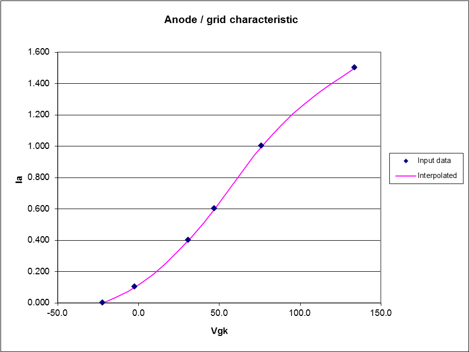 |
Fig 3 shows the anode current / grid voltage transfer characteristic derived from the load line in Fig 2. It is not perfectly linear, no practical device is perfectly linear. The departures from linearity are both at the low and and the high end. The graph was produced using RF Power Amplifier Tube Performance Computer.
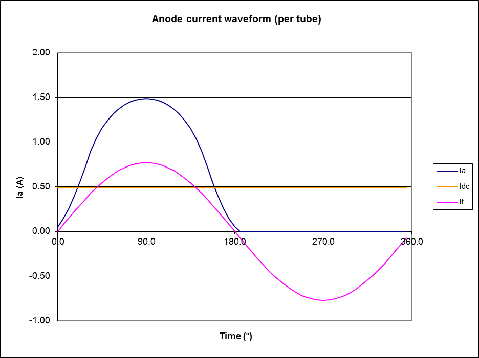 |
Fig 4 shows the modeled anode current waveform that would result from sinusoidal voltage drive of the grid-cathode. As might be expected from Fig 3, the anode current wave shape is not perfectly sinusoidal (apart from the Class B conduction angle), it has visible distortion present near zero and at the high end. Both of these contribute to harmonic distortion, and in the case of a complex wave excitation, IMD. The graph was produced using RF Power Amplifier Tube Performance Computer.
The definitive test is measurement of IMD achieved under given operating conditions.
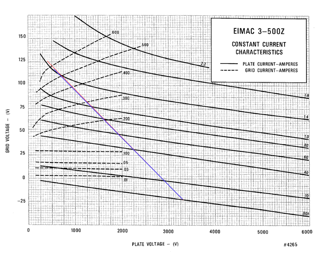 |
In real life, the load line is quite sensitive to the way in which the power amplifier is loaded and driven. Good practice is to load and drive for maximum power output, then slightly over couple the output circuit for a small reduction in power output (say 5%) which has the effect of moving the left hand end of the load line rightwards along the constant grid voltage line, see the blue load line in Fig 5, which improves high end linearity and reduces peak grid current (by about 15% in this example).
From time to time, threads flare up on the subject, usually with the same protagonists arguing their perspective on the design of a particular commercial power amplifier. (eHam 2013) is a recent and typical thread discussing specifically the Ameritron AL80B which uses a 3-500Z (used for the examples above), and it illustrates some of the common thinking that is applied to the problem.
The discussion is around 1000W PEP output, which implies the application is SSB telephony.
Some quotes are given from the thread below.
W8JX:
The tube is "rated" for 400ma max and higher currents can shorten its life. The way to "safely" get more power out of a single tube is to raise its plate voltage not its plate current for what its worth.
As explained above, the 400mA is a DC rating that is somewhat indirect and the implied instantaneous peak cathode current (which is the issue, not plate current) is inconsistently rated from application to application within the same datasheet.
No evidence is offered of shortened life, just a fear factor that higher
currents can shorten its life
.
W8JX:
The cathode is not immune either to higher current rates and higher rate can cause the tube to "soften" sooner due to reduced emissivity of cathode
The effect described is a property of coated cathodes, and the valve being discussed uses a thoriated tungsten filament that is not subject to that damage mechanism.
AD4U:
IMO the issue is exceeding EIMAC's published maximum (do not exceed under any circumstances) plate current rating of 400 mA per tube.
Again, a DC rating that is somewhat indirect and the implied instantaneous peak cathode current (which is the issue, not plate current) is inconsistently rated from application to application within the same datasheet.
AD4U:
In order for a device to be used as a LINEAR amp I was taught that the device must be operated within the linear (straight line) part of the device's characteristic curve. When the device is driven to the point where it is being operated out of the linear part of the curve, which is most often high plate or collector current, the device is no longer considered to be a LINEAR amp. That is why when IN MY OPINION any 3-500Z is used in a LINEAR amp it should be operated within the linear portion of the curve. In EIMAC tubes that used to be up to around 400 mA of plate current.
As AD4U acknowledges elsewhere, no device is perfectly linear, and he provides no evidence that the departure from linearity is excessive. If one observes Fig 3, the Ia/Vg transfer characteristic along the load line departs from a straight line at the low end and at the high end. The low end departure is not very sensitive to the choice of peak anode current, and under SSB telephony contributes much of the IMD products of the power amplifier because of the tendency to operate in that part of the curve for much of the time in telephony, albeit at lower power.
In real life, the load line is quite sensitive to the way in which the power amplifier is loaded and driven. As explained earlier, good practice is to load and drive for maximum power output, then slightly over couple the output circuit for a small reduction in power output (say 5%) which has the effect of moving the left hand end of the load line upwards and rightwards which improves high end linearity,
W8JX:
cathode current and excessive plate/cathode current can in theory strip minute parts of filament/cathode coating away leading to tube loosing emissivity prematurely and going soft
Repetition of the error that thoriated tungsten filaments are subject to stripping of a coating that does not exist. Repetition is a common tactic in online discussions, there is a notion that the more times something is said, the truer it is... which is of course nonsense.
A reader might wonder at the motivation for the OP's question since the manual (which is available online) gives quite detailed answers.
Datasheets often have recommendations for specific applications, and they provide guidance for designers who do not want to dig deeper.
Datasheets may not provide all key not-to-exceed data directly, but some critical parameters are implied by application specific recommendations in the datasheet, and they can be extracted with a little creating thinking.
The critical parameters are implied by application specific recommendations in the datasheet, are often inconsistent, but the maximum value of each parameter can usually be taken as the applicable value.
Recommendations for amplitude modulated Class C are often provided and imply values for maximum instantaneous anode to cathode voltage, and instantaneous maximum cathode current which are properties of the valve rather than the application.
Operating outside of application specific recommendations is not necessarily bad, but it is foreign to many less experienced commentators and designers.
| Version | Date | Description |
| 1.01 | 19/04/2013 | Initial. |
| 1.02 | ||
| 1.03 |
Use at your own risk, not warranted for any purpose. Do not depend on any results without independent verification.
© Copyright: Owen Duffy 1995, 2021. All rights reserved. Disclaimer.