 |
| OwenDuffy.net |
|
A question recently asked in an online forum was:
Since I built my first 80meter/40meter 6aq5 + 6DQ6 transmitter with pi output in 1972, when I want to vary the inductance of a coil in a tunner, or loading coil in an antenna, I just short circuit some turns.
I see that this is the usual practice everywhere.
My question is why do we not just leave the turns open circuited instead of short circuiting them.
It appears to me that in the short circuited turns, a very big current must be circulating, adding heat losses and lowering the Q of the circuit.
It is an interesting question, and one that is easily explained by basic AC circuit theory.
The first question was why not leave the unused turns open circuit.
The reason is that the voltage induced in the unused turns can be very high, extreme in the case when tapped close to the other end, and a challenge for switch insulation, coil insulation etc.
The induced voltage can be calculated easily using basic AC circuit
theory.
A simple model can be constructing by making some assumptions:
Wheeler's formula estimates the inductance of an air cored single layer solenoid as L=µ0*π*N^2*r^2/(l+0.9*r) where L is in H, N is number of turns, r is the radius of the solenoid in metres, l is the height of the solenoid in metres.
Wheeler later published his continuous inductance formula, L= µ0*N^2*r*(ln(1+pi*r/l)+1/(2.3004+1.6*l/r+0.4409*(l/r)^2)), which is more accurate for the short inductors in this analysis.
The technique is to choose a practical example coil, and for a range of tapping positions, to calculate inductance of each section of coil L1 and L2 as an independent inductors using Wheelers formula, and knowing (from Wheelers formula) the inductance of the coupled combination, calculate the mutual inductance M between the sections.
From L1, L2 and M, we can calculate form a T equivalent circuit for the coupled coil sections, and calculate the current in the shorted turns relative to the current in the other part of the inductor.
Assuming that loss resistance is proportional to the length of wire, the relative loss in the shorted turns can be calculated.
|
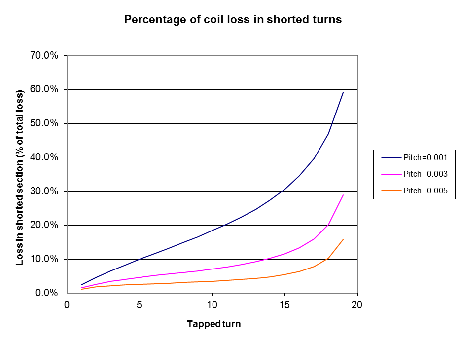
Fig 1 shows the loss in the shorted turns as a percentage of total loss for an air cored inductor of 20 turns, 50mm diameter, and various winding pitches (metres per turn).
It can be seen that for closer spaced windings (smaller pitch), loss is higher. The inductor sections are more tightly coupled, higher flux linkage, more current flows in the shorted turns, and loss is higher.
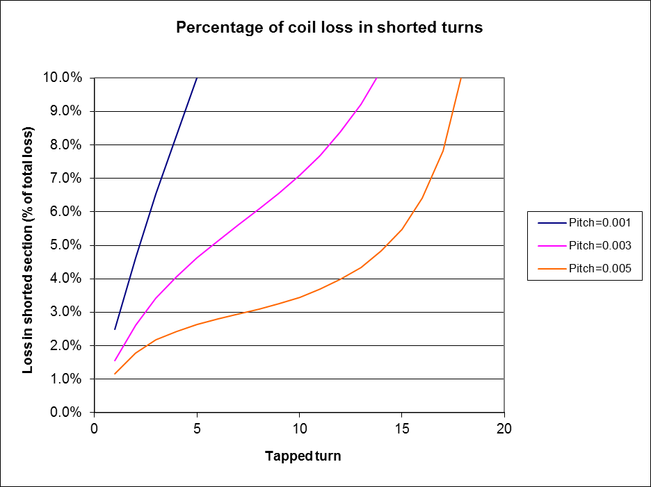 |
Fig 2 shows the same data with an expanded scale. It can be seen that loosely coupled turns give rise to lower loss, and avoiding shorting few turns helps to keep losses lower.
The flux coupling factor k for the blue line is about 0.47. Higher
coupling factors, as might be obtained using a magnetic core, will
result in higher relative loss in the shorted turns.
Note that the model shorts only the tapping point to the coil end, and intermediate tap points are left open.
So, in answer to the question, yes a very large circulating current can flow in the shorted turns. The circulating current is highest for tightly coupled turns, and when very few turns are shorted. In this situation, resistance of the shorted turns is relatively low, but current square may be relatively high. Fortunately, many applications do not call for shorting very few turns.
Note that shorting just one end turn has a dramatic effect on
inductance when the coupling factor is high, so not only is it
potentially lossy, the reduction in inductance may be more than
desired. Lower coupling factor tames this behaviour, but at the expense
of a physically larger inductor.
Tapping a coil and leaving unused turns open can create high voltages in the unused turns, worst when the coil is tightly coupled and the tapping point is near to the other end of the coil.
Shorting unused turns is practical on coils where flux coupling is not high, and losses are lowest when tapping points that give rise to very few shorted turns are avoided.
Otherwise, use separate uncoupled inductors.
| Version | Date | Description |
| 1.01 | 19/10/2010 | Initial. |
| 1.02 | 02/11/11 | Revised to use Wheeler's Continuous Inductance Formula |
| 1.03 |
© Copyright: Owen Duffy 1995, 2021. All rights reserved. Disclaimer.