 |
| OwenDuffy.net |
|
It is not unusual to hear of disappointing efficiency in grounded grid Class B (or AB) single ended triode RF power amplifiers. This article explores a possible cause.
Class B denotes an amplifier where the active device conducts for exactly 180° of the input sinusoidal cycle. In practical RF power amplifiers, the conduction angle is a little more than 180°, and technically Class AB, but both practical Class AB amplifiers and practical Class B amplifiers are close enough to Class B to be treated as Class B for the purposes of this article.
|
|
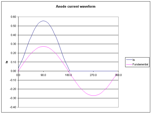
Fig 1 shows the anode current waveform of a typical Class B RF power amplifier in blue, and the fundamental component in magenta. The anode current is rich in harmonics.
 |
Fig 2 shows the spectral content of the anode current in Fig 1; f0 is the DC component, f1 the fundamental etc. Note that the second harmonic is over 40% of the amplitude of the fundamental.
The efficiency of a Class B amplifier derives from the relationship between the DC component of anode current, and the fundamental component of anode current. In the chart above, the DC component is 65% of the fundamental component whereas in a Class A amplifier, it would be less than more than 100%, meaning higher DC input power in Class A for the same RF output power.
The cathode current in a grounded grid triode amplifier is the sum of the anode current and grid current. Grid current increases dramatically as anode-cathode voltage decreases towards the grid-cathode voltage, so grid current is very 'peaky' in its waveshape, even richer in harmonics than anode current, and so cathode current is a little richer in harmonics than anode current.
Any impedance appearing in the cathode circuit of a grounded grid amplifier causes negative feedback, it tends to reduce the gain of the stage.
Sure, some cathode circuit impedance is unavoidable, and typically at the fundamental frequency, it is likely to be of the order of 50Ω transformed by the input network.
Cathode degeneration can frustrate development of the Class B anode current wave shape. Reducing gain at the harmonics by cathode degeneration will cause the anode current waveform to be closer to an undistorted sinusoid than is required for true Class B operation. The result of this is that the DC component of the modified waveform is higher relative to the fundamental component, and more DC input power is required for the same RF output power, reducing efficiency.
The answer lies in ensuring that the impedance looking back from the cathode to the exciter is very low at harmonic frequencies for all operating bands. Most good solutions for the second and third harmonics usually deal with the higher order ones.
Different input networks are used in different designs, and indeed, some designs do not incorporate an input network to speak of within the PA.
A low pass pi network will be used to explore some effects of the input network.
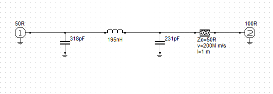 |
Fig 3 is a model of a low pass pi input network for a PA. The network has been designed to transform a cathode driving impedance of 100Ω to an input impedance of 50Ω. The input network has been connected to the cathode using 1m of 50Ω coax.
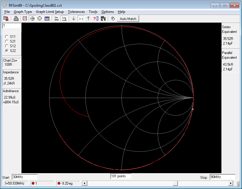 |
Fig 4 shows a simulation of the network. The impedance looking back from the cathode at the second harmonic (60MHz) is 35-j1200Ω. This will reduce the second harmonic component of current dramatically, and near Class A conditions (including low efficiency) will prevail.
The scenario for a PA with no input network, and a coax connection of moderate length to an exciter is somewhat similar. (This configuration is quite popular in the ham literature.)
Designs that do not include an input network are designed to fail. Sure, they deliver RF, but they are unlikely to deliver Class B performance.
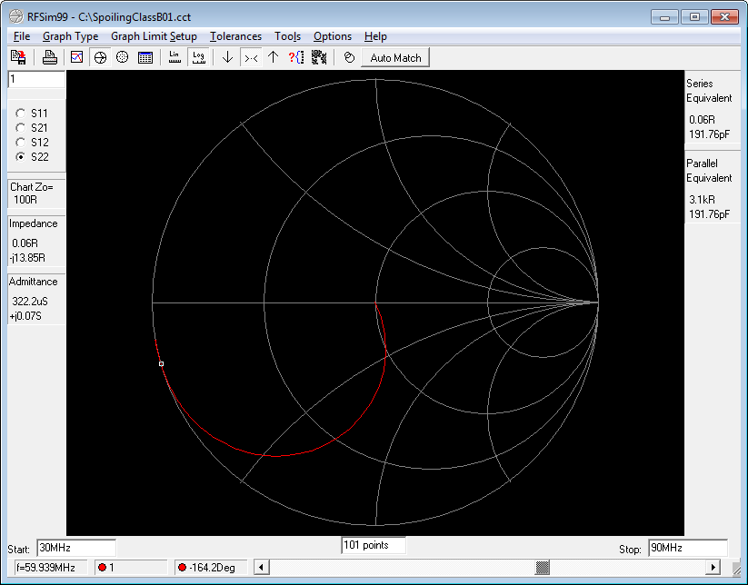 |
Fig 5 shows the same network with the coax section eliminated. The impedance looking back from the cathode at the second harmonic (60MHz) is 0.1-j14Ω. (The network model is lossless, in practice the R component will be a little higher than 0.1Ω). The cathode degeneration resulting from such a low impedance will be quite small.
Other network configurations that do not offer a very low impedance at the second and higher harmonics are not well suited to this application. For example, a low pass T network has an input impedance that increases with frequency above the cut-off.
(Measures 1994) proposes adding a resistor between the input network and
cathode: [t]he fix is simple: connect a 40-ohm resistor in series with each
3CX800A7 cathode. These [cathode RF negative feedback] resistors reduce gain
.
Whilst he makes claim of several advantages of using cathode resistors, he does
not report the effect on efficiency which can be expected to be a casualty of
this modification to the amplifier. If an input attenuator is needed, it should
be on the input side of the input network.
| Version | Date | Description |
| 1.01 | 12/09/2011 | Initial. |
| 1.02 | ||
| 1.03 |
© Copyright: Owen Duffy 1995, 2021. All rights reserved. Disclaimer.