 |
| OwenDuffy.net |
|
(CPI/Eimac 2010) and (CPI/Eimac Jan 2005) explain that the life of tubes using Thoriated Tungsten filaments can be extended significantly in some applications by careful management of filament voltage to heat the filament no higher that necessary to support the application requirement for space charge, but always a safe margin above the voltage that would allow poisoning of the filament.
The paper explains the failure mechanisms of the filament in power grid tubes. Of particular relevance to this article (though not the only failure mechanisms) are:
(CPI/Eimac/Econco nd) explains that emission loss by de-carburisation is more
likely in broadcast applications In broadcast transmitters that operate into
a fixed load, the vast majority of failures result from a loss of emission
caused by decarburization. Industrial applications, such as dielectric or
induction heating, often experience a higher percentage of catastrophic failures
.
Loss of emission caused by decarburization is probably less significant in amateur applications
where the filaments are commonly cycled for perhaps an hour or two of operation
leading to earlier open circuit failure of the filament.
A foreword on safety. Tube amplifiers operate at high voltages, typically some thousands of volts, and have power supplies that can sustain sufficient current to kill a person. When the covers are removed they are a serious hazard, even for some time after power has been disconnected. Inform yourself of the hazards and methods of control of those hazards before commencing any work. Be warned!
The best information on Eimac/CPI's recommendation is to read their papers (CPI/Eimac 2010) (CPI/Eimac 2005) and (CPI/Eimac/Econco nd) and the relevant tube datasheet. Nevertheless, this section will flag some of the key issues in implementation in a typical commercially manufactured amateur transmitter.
(CPI/Eimac Sep 2010) and (CPI/Eimac Jan 2005) state:
A means must be provided to hold filament voltage constant. If the filament voltage is permitted to vary in accordance with primary line voltage fluctuations, the effect on tube life can be devastating. ...
NOTE: If the filament voltage cannot be regulated to within ± 3%, the filament should always be operated at the rated nominal voltage specified on the data sheet. It should be noted that there is a danger to operating the emitter too much on the “cold” temperature side. It may become “poisoned.” A cold filament acts as a getter; that is, it attracts contaminants. When a contaminant becomes attached to the surface of the emitter, the affected area of the emitter is rendered inactive, causing loss of emission.
Since most amateur transmitters do not have a regulated supply for the filament, this prompts thinking about the AC mains voltage regulation, the further regulation issues within a transmitter due to shared transformers, wiring, filament chokes etc.
Under (ANSI C84.1-2006), the service voltage under "Condition A" could range from 126 to 114 for a nominal 120V service, double that for a nominal 240V service. This is a band of ± 3% before voltage drop within the customer premises is added.
(NEC 1999) requires that the voltage drop in feeder and branch circuit could be up to 5%, 3% in the branch circuit alone.
If the change in load from receive to transmit was large (as it would be in most cases of a dedicated circuit with no other high power loads, you could easily find that at light load times, equipment voltage might be 126/252V, and at high load times on tx, equipment voltage might be as low as 110.8/221.6V which reconciles reasonably with (ANSI C84.1-2006) specification of minimum utilisation voltage of 110/220V. The situation could be worse on a compliant service with a shared feeder.
Further variation may be caused by a transformer shared for other than the filament load.
The mains supply does not usually offer a source regulated to ± 3% or better.
Much of the world is harmonising on supply voltages standarised by (IEC60038 2009).
For a nominal 230V supply system, the specified highest utilisation voltage is 253V, and the lowest is 198V.
Further variation may be caused by a transformer shared for other than the filament load.
The mains supply does not usually offer a source regulated to ± 3% or better.
Clearly, mains doesn't vary all the way from one permitted limit to another. It should almost always be within the appropriate limits, but variation will depend on the natural voltage drop of distribution lines and the thresholds and operation of tap changing transformers in the system.
It may be challenging to guarantee that 3-500Z filament remains within Eimac specs with an ordinary mains service at some locations. You would only know by conducting a survey of mains voltages under a range of load conditions.
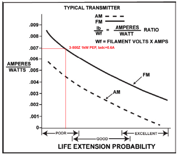
(CPI/Eimac Sep 2010) suggests that the likely benefit of a filament
management regime is indicated from the quantity Divide the average anode
current in amperes by the product of filament voltage and current.
The
average anode current is the DC anode current, so whilst one expects that the
filament needs to be hot enough to support the instantaneous space charge demand
(cathode current), it seems that they have factored in some allowance for grid
and screen current, and peak to average ratio. Even with that, it is hard to understand the
relationship of their curves for FM and AM.
|
Fig 1 above is from (CPI/Eimac Sep 2010) with the operating point for a 3-500Z added. The graph does not specifically provide for Class AB or Class B SSB operation, so the conservative position is to use the FM curve for SSB PEP.
Taking the example of a 3-500Z at 0.5A DC anode current for 1kW output. The filament rated for 14.6A at 5V, so 73W. At 0.5A DC anode current the ratio Iadc/Pf=0.00685. That condition is plotted on Fig 1 in red, and the indicated probability of life extension is poor, less than good.
Is some adjustment warranted because of the different form factor of anode current or cathode current in Class B (or near to it) compared to Class C (at an unspecified conduction angle)? The article doesn't provide guidance, but the graph is only intended to identify the probability of life extension.
Factors that might reduce the prospect for life extension include:
Note that Eimac's discussion is always about controlling filament voltage not current. Filament current increases as de-carburisation progresses through life, and notwithstanding that, filament voltage may need to be increased further to obtain adequate emission towards end of life.
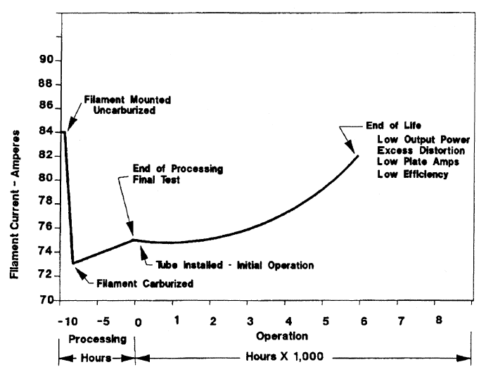 |
Fig 2 from (CPI/Eimac/Econco nd) 4CX5000A shows filament current to increase by about 10% through life. The use of a simple series resistance to reduce filament voltage will require more frequent adjustment as the filament current at constant voltage increases with de-carburisation, which brings about the requirement for monitoring through life.
(Measures 2004) states According to Eimac®, each 3% increase in
filament-voltage, above what is needed to achieve full power output, will reduce
the useful emission life of a directly heated amplifier-tube by one-half. The
bottom-line is that at 5.3V the useful emission life of the 3-500Zs will be
reduced to about one-sixth of what could be realized if the filaments were
operated at 4.8V
. He does refer to the optimum 4.8V
, again without
explanation of how he arrived at that.
(Measures 1994) offers [i]f you are into math, cathode life is
proportional to [E1/E2]23.4 - where E1 is the lowest filament voltage
at which normal PEP output is realized - and E2 is the increased filament
voltage
, but gives no reference or explanation. By this formula, if voltage
is reduced by a factor of 1.03^2 or to 94.3% (assuming emission is not
temperature limited), Measures' formula gives a life of 390%.
Measures does not give specific reference, but (Eimac 2003) states
Theoretically a 3% increase in filament voltage will result in a 20º Kelvin
increase in temperature, a 20% increase in peak emission, and a 50% decrease in
life due to carbon loss. This, of course, works the other way, too. For a small
decrease in temperature and peak emission, life of the carbide layer and hence
tube life can be increased by a substantial percentage
, but that is not
quite the same as Measures' loose paraphrase. (Eimac 2003) then refers the
reader to AB18 for detailed information.
If the filament life theoretically increased at the rate of 50% for every 3% reduction in filament voltage, reducing filament voltage by a factor of 1.03^2, would result in life of 1.5^2=225%, much less than Measures' formula which gave 390%.
Similarly, if the filament life theoretically increased at the rate of 50% for every 3% reduction in filament voltage from 5.3V to 4.8V (and assuming that 4.8V was sufficient that emission was not temperature limited), then by calculation, the life at 4.8V would be 1.5^(LOG(5.3/4.8)/LOG(1.03))=3.9 times the life at 5.3V, not 6.0 times as claimed by Measures.
Whilst 4.8V (at the socket though) is within Eimac's stated 3-500Z
specification, it does not necessarily guarantee the target power with
acceptable IMD in all applications, and that it suits other tubes of the same
type , in fact (CPI/Eimac 2010) warns Voltage levels required with one tube
do not apply to a replacement tube
. In fact, Eimac explain that running a
new tube on reduced voltage prevents it achieving full emission, they recommend
100 to 200 hours at rated voltage before commencing filament management.
QST October 2011 issue carries a story (Rankin 2011) under the synopsis Are you running your amplifier filament voltage too high? This simple fix can
extend your amplifier tube life, perhaps by a factor of 10
.
Rankin sets the scene for his article be describing the problem to be
solved, an apparent sudden open circuit filament my first thought was that
the filament supply had died
, one assumes the filament that can normally be
seen very clearly from outside the case was not glowing. He then reports
measurement of the filament voltage at the tube end of the filament choke (and
not at the tube socket as stipulated in (Eimac 1980) was 50mV higher than the
high end of the permitted range. The instrument used appears to not be a true
RMS responding instrument, so that introduces more scope for error. He has not
reported the supply voltage and transformer tap settings. All in all, the
information presented is not as complete as one might hope, and is less than
compelling. It would seem unlikely that filament supply at the voltage suggested
would burn a filament out as suggested.
Rankin says When my amplifier is operated from 240V 60Hz, the
measured 5.3V exceed's Eimac's maximum filament voltage (4.8 V) by 0.5V or
10.4%. Per Eimac's application note this could shorten the tube life by a factor
of 10. This means buying 10 times as many tubes over the life of the amplifier.
but that is not supported by available 3-500Z data sheets which state clearly
that filament voltage is 5.0V +/- 0.25V, and in more detail (Eimac 1980, p4)
states Filament voltage as measured at the socket must be maintained within
the range 4.75 to 5.25 volts to obtain maximum tube life
.
The claim of a tenfold increase in life is not substantiated and seems extravagant based on (Eimac 2003, p163).
Rankin says [a]ccording to Eimac, each 3% increase in filament voltage,
above the 4.8V needed to achieve full power output will reduce the emission life
of a directly heated amplifier-tube by 50%
. He gives no reference where
Eimac literally says that, it is probably Rankin's construction.
Rankin seems to have picked a target voltage (4.8V) without clear reason and set about reducing the filament voltage to that amount (or indeed a little lower) without following Eimac's quite detailed process for discovering the optimum regulated voltage that delivers target power with acceptable IMD. It appears that Rankin has depended on Measures' opinion that 4.8V is optimal for all 3-500Z tubes, and Measures doesn't explain how he came to that value, or why it suits all tubes of that type.
The instrument used by Rankin appears from the pictures to not be a true RMS responding instrument, so that introduces more scope for error. No mention is made of whether the voltage measurements are made with filament only load, or with the PA operating. The measurement setup suggests filament only load. No statement is made of the transformer tap, readers will probably assume that it is set to 240V.
Though (Rankin 2011) attributes things to Eimac, he gives a reference to only one paper, (Measures 2004) which itself attributes things to Eimac without specific references.
Interesting to compare (Rankin 2011), (Measures Mar 2004) and (Measures Oct 2004) prediction of the effect of 5.3V, one estimates a 10 fold reduction in life, the next six fold, and the third an eight fold reduction in life. No explanatory detail or justification in either paper.
QST in publishing the article lends a certain recommendation to the content. Readers might properly consider the merit of the article, and the credibility of QST.
(Rankin 2012) makes only one admission of technical error. He offers that he
depended on a copy of an article (Conroy 2003) for specification of the
recommended filament voltage range for a 3-500Z, apparently preferring that
source to researching a 3-500Z datasheet, and admits that Eimac recommends
5V+/-5%, and that his article
, though only appears
so, as if he is not really convinced.appears
to be wrong about the filament
voltage
(Conroy 2003) states:
One of the most important things is filament voltage. A 3-500Z has a minimum of 4.8V with a max of 5VAC. If there is a 3% increase above 5VAC, it will decrease the life of the tube by one half. I measured the voltage of mine and it was 5.2volts, which is way to high. I replaced the filament wire with 24AGW and added some resistive wire to one end. Using smaller wire is much easier then trying to find a .25ohm resistor. This brought it down to a perfect 4.8VAC. Even worse than 3% higher voltage is a under voltage. That will literally kill the tube in a very very short time.
He writes with an authoritative tone, and gives no references, but is inconsistent with published 3-500Z datasheets.
There are serious hazards in working on tube amplifiers, inform yourself and control those hazards.
There is no substitute for reading Eimac's several papers on filament management to extend tube life, not this article, not QST.
Amateur applications might not lend themselves to high probability of life extension using Eimac's filament management program. Indeed no evidence has been presented by Measures or Rankin that their 3-500Z example achieved any measured life improvement.
There is a very real risk that despite extravagant claims, inexpert intervention might actually degrade IMD performance and worsen tube life, and the latter may have tube / amplifier warranty implications. Indeed plugging a new tube into the modified amplifier goes against Eimac's recommendation to run at rated voltage for the first 100 to 200 hours.
| Version | Date | Description |
| 1.01 | 28/09/2011 | Initial. |
| 1.02 | 17/12/2011 | Updated. |
| 1.03 |
© Copyright: Owen Duffy 1995, 2021. All rights reserved. Disclaimer.