Telegrapher's Equation
| This article outlines a derivation of Oliver Heaviside's Telegrapher's Equation and application to solution of steady state transmission line problems. |
Introduction
A transmission line can be represented as an infinite series of cascaded identical two port networks each representing an infinitely small section of the transmission line. The small networks represent:
- the distributed resistance of the conductors is represented by a series resistance per unit length R
- the distributed inductance is represented by a series inductance per unit length L
- the capacitance between the conductors is represented by a shunt capacitance per unit length C
- the conductance of the dielectric material separating the two conductors is represented by a conductance per unit length G
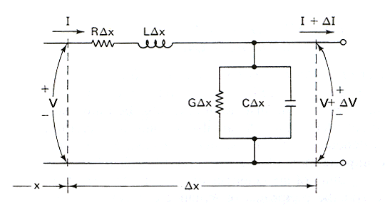 |
Fig 1 shows the small networks.
R,L,G, and C may be frequency dependent. In practical transmission lines at HF and above the following assumptions are often appropriately used:
- inductance per unit length as constant (due partially to skin effect and a fully effective outer conductor));
- capacitance per unit length as constant;
- resistance per unit length is subject to skin effect and is proportional to the square root of frequency;
- conductance per unit length is due to dielectric loss and is proportional to frequency.
Derivation
The line voltage V(x) and the current I(x) where x is displacement can be expressed in the frequency domain as:
\[\frac{\partial V(x)}{\partial x}=-(R+j \omega L)I(x)\]
\[\frac{\partial I(x)}{\partial x}=-(G+j \omega C)V(x)\]
Differentiating both:
\[\frac{\partial^2 V(x)}{\partial x^2}=\gamma^2V(x)\]
\[\frac{\partial^2 I(x)}{\partial x^2}=\gamma^2 I(x)\]
where:
\[\gamma=\sqrt{(R+j \omega L)(G+j \omega C)}\]
\[Z_0=\sqrt{\frac{R+j \omega L}{G+j \omega C}}\]
γ is the transmission line complex propagation constant, and Z0 is a complex value known as the characteristic impedance of the line.
A solution for V(x) and I(x) is:
\[V(x)=V_f e^{\gamma x}+V_r e^{- \gamma x}\]
\[I(x)=I_f e^{\gamma x}-I_r e^{- \gamma x}\]
where x is the displacement from the load, negative towards the source, and Vf, Vr, If and Ir are forward and reflected voltages and currents respectively at the load end of the line.
Application
The above expressions can be rewritten as:
\[V(x)=V_f( e^{\gamma x}+ \Gamma e^{- \gamma x})\]
\[I(x)=I_f( e^{\gamma x}- \Gamma e^{- \gamma x})\]
where Γ is the complex reflection coefficient at the load.
Transmission line behaviour is described by these equations and the boundary conditions imposed by the load.
Given load impedance Zl=V/I:
\[\Gamma=\frac{Z_l-Z_0}{Z_l+Z_0}\]
\[\Gamma(x)=\Gamma \frac{e^{\gamma x}}{e^{- \gamma x}}\]
These equations fully describe the behaviour of a transmission line with a given load impedance.
From these, the relationships for rho; and VSWR can be developed:
\[\rho=|\Gamma|\]
\[VSWR=\frac{1+\rho}{1-\rho}\]
We can write \(Z_l \text{ in terms of } Z_0 \text{ and } \Gamma \):
\[Z_l=Z_0\frac{1+\Gamma}{1-\Gamma}\]
Input impedance Zin of line of length l can be calculated from the load impedance:
\[Z_{in}=Z_0 \frac{Z_l+Z_0 tanh(\gamma l)}{Z_0+Z_l tanh(\gamma l)}\]
In the special case of a lossless line, input impedance Zin of line of length l can be calculated from the load impedance:
\[Z_{in}=Z_0 \frac{Z_l+\jmath Z_0 tan(\beta l)}{Z_0+\jmath Z_l tan(\beta l)}\]
The following relationships exist for the two port network equivalent of a transmission line:
\[V_1=V_2 cosh(\gamma l)+I_2 Z_0 sinh(\gamma l)\]
\[I_1=\frac{V_2}{Z_0} sinh(\gamma l)+I_2 cosh(\gamma l)\]
where V1 and I1 are the voltage and current at the input port, and V2 and I2 are the voltage and current at the output port.
LINKS
Glossary
| Term | Meaning |
| γ | The complex line propagation constant. |
| Γ | The complex reflection coefficient (a complex quantity with real and imaginary parts) |
| Distortionless line | R/L=G/C. A lossless line is a special case of a distortionless line. |
| Lossless line | R=0, G=0 |
| ρ | The magnitude of Γ |
| VSWR | Voltage Standing Wave Ratio is the ratio of the voltage maximum (antinode) to the adjacent voltage minimum (node) on a transmission line |
Changes
| Version | Date | Description |
| 1.01 | 09/04/2008 | Initial. |
| 1.02 | 03/01/2021 | Mathjax |
| 1.03 |