 |
| OwenDuffy.net |
|
| A recent discussion with another amateur gave me reason to revisit a Dec 1993 QST "New Ham Companion" article entitled "The Lure of Ladder Line" (Ford 1993). In the article, author and assistant technical editor Steve Ford (WB8IMY) describes the benefits of ladder line in feeding a 20.1m (66') centre fed dipole for multi-band use on HF. The claimed performance on the 80m band seemed inconsistent with my experience that where a centre fed dipole less than about 0.35λ in length, it is difficult to achieve acceptable feed system efficiency in practical configurations. |
The antenna described in the QST article is 20.1m (66') long, at a height of 9.1m (30') above ground, and fed in the centre with 15.2m (50') of coax / ladder line.
The antenna model discussed in this article is consistent with the above, and additionally, ground &epsilon=13, σ=0.05, conductor 3mm (1/8") diameter, and RG-213/U / Wireman 551 ladder line. A lossless balun is assumed.
This model also includes a practical L match. The L match used for tuner loss is in general, the most efficient way to transform the load impedance. Using the loss of a practical L-match tends to underestimate the loss in any other tuner configuration.
The NEC model deck is available.
This analysis does not consider directivity, or polar pattern of the radiator, or degradation of ladder line performance when wet.
Steve was looking for a low impact, multi-band HF antenna and had a notion that "Perhaps I could string up a single dipole and feed it with coaxial cable, using an antenna tuner to tune it on several bands." He implemented such a system and used it on 40m up to 10m, citing 75 new countries for a DXCC as evidence that it "worked".
Steve's article used RG-8/U coax which has a nominal Zo of 52Ω. This analysis uses the more popular 50Ω RG213/U, but losses are very similar to RG-8/U.
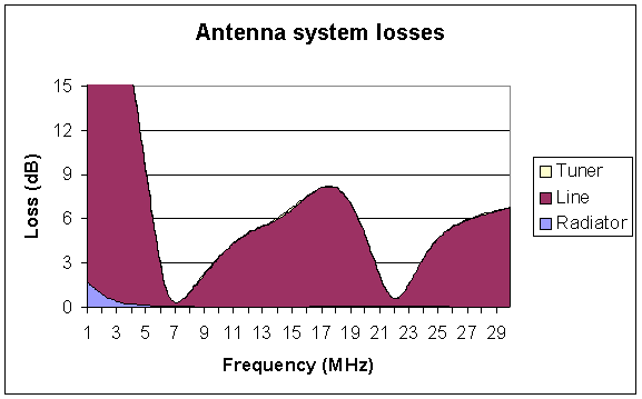
Figure 1 shows the results of modelling the coax feed configuration using 15.2m (50') of RG-213/U. The graph shows the principal components of antenna system loss over the frequency range of 1 to 30Mhz. The losses reported here are much higher than in the QST article, eg line loss of 17.2dB at 3.8MHz against QST's 13.7dB.
|
Clearly, this configuration has very high losses on all bands except 7MHz and 21MHz.
A similar coax feed arrangement using the lossier RG-58C/U is shown in Figure 1a.
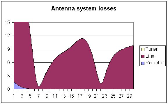 |
This configuration has all the same problems of the RG-213/U feed in Figure 1, just that it is even worse.
The coax feed performance highlights that:
On the advice of a peer, Steve then explored the same antenna with 15.2m (50') of ladder line. The article presents some predicted feed line losses at spot frequencies in the main HF bands.
Figure 2 shows the results of modelling the ladder line feed configuration using 15.2m (50') of Wireman 551. The graph shows the principal components of antenna system loss over the frequency range of 1 to 30Mhz. The losses reported here are much higher than in the QST article, eg line loss of 5.4dB at 3.8MHz against QST's 1.37dB.
Notwithstanding comments in the reference article, the configuration does not have acceptable losses on 80m and 160m. Antenna system loss on 1.8MHz is 19.6dB, and on 3.6MHz is 6.5dB.
The configuration does provide quite acceptable multi-band antenna system loss on all HF amateur bands from 60m to 10m.
The radiator behaves as a low dipole. At frequencies where it is relatively short, the pattern is nearly omni directional, and the pattern transitions to multiple lobes and nulls at frequencies where the dipole it is multiple wavelengths long.
Figure 2 shows the principal components of antenna system loss over the frequency range of 1 to 30Mhz.
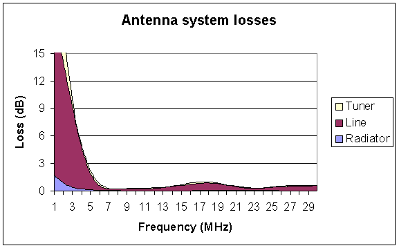 |
Clearly, this configuration has very high losses on bands below 5Mhz, but is quite acceptable at and above 5MHz.
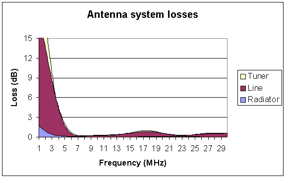
Critics have suggested that selection of Wireman 551 (the "original" ladder line) exaggerates losses. Figure 3 shows the principal components of antenna system loss over the frequency range of 1 to 30Mhz for Wireman's most expensive ladder line, #554. The modelled losses are slightly better with 554, but for example, the improvement of 0.03dB at 7MHz is so slight that it is not readily visible in the chart, and is not reason alone to pay more than twice the price.
 |
Inconsistencies were noticed between line losses reported in the QST article, those calculated here, and published line loss specifications.
The QST article gives a ladder line loss for what should be close to a 75+j0 load at 7.15MHz of 0.07dB which is much better than:
The QST ladder line losses seem overly optimistic, perhaps they forgot to allow for the additional loss under high VSWR, or their method of accounting for mismatch is flawed.
There is a reference in the text to the RG-8/U coax having loss of less than 1.5dB/100' according to the ARRL Handbook chart (whereas the matched line loss is more like 1.9dB/100'). This error would flow into any calculation of load under mismatched conditions.
A later article (Ford 1994) "Get out your calculators or computers" picks up on the earlier article and changes the configuration, which muddies the waters a little. They report a modelled feed point impedance at 3.8MHz of 10.3-j878.8 and 100' of ladder line having a line loss of 2.2dB. Again, using N7WS's characterisation of Wireman 551, the line loss would be 4.5dB. The same article quotes a line loss of 18.1dB using RG-213/U whereas using Belden's published figures for 8267 (RG-213/U), the line loss would be 15.8dB.
 |
The differences seem to be in the characterisation of the lines (coax and ladder line), and in the transmission line loss models that were employed.
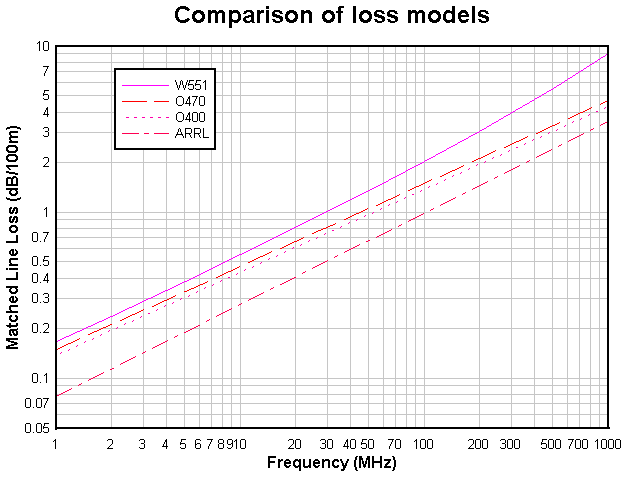
Figure 4 shows a comparison of loss models for four open wire lines:
It is unlikely that the ARRL's generic ladder line (450Ω ladder line (25mm / 1.02mm or 1" / #18) has loss lower than the theoretical losses for an air dielectric line with the same conductors. The conductors for a 19mm spaced line need to be at least 2mm diameter (#12) to deliver the loss that ARRL specifies. Perhaps the ARRL handbook is not a good reference for matched line loss, and further scope for error occurs where the loss under high VSWR is estimated.
The analysis is based on an NEC model of the radiator. The NEC model of the dipole is available here. NEC2 was called from a custom Perl script that created the Sommerfield ground model and run NEC2 to create a report of feed point impedances from 1MHz to 30MHz in 0.1MHz steps.
A Perl script was written to parse the NEC report, and do the transmission line calculations (impedance transformation, loss, voltage etc) and L-Tuner simulation. The results were written to a tab delimited text file which was loaded into Excel for the final analysis and graphics.
Transmission line parameters come from the Transmission Line Loss Calculator.
(Note that none of the results depend on approximations based on VSWR.)
| Version | Date | Description |
| 1.01 | 13/10/2005 | Initial. |
| 1.02 | 15/11/2005 | Added April 1994 QST reference. |
| 1.03 | 17/11/2005 | Added RG-58C/U analysis. |
© Copyright: Owen Duffy 1995, 2021. All rights reserved. Disclaimer.