 |
| OwenDuffy.net |
|
In testing electric drive systems (ESC + BLDC motor), a repeatable scenario was needed to evaluate changes such as changes to commutation advance.
Often these changes have different impact under rapid acceleration or deceleration to slower changes.
This article describes a simple servo signal ramp generator based on Arduino hardware, in this case using an Arduino Nano but most Arduinos or clones could be used or adapted.
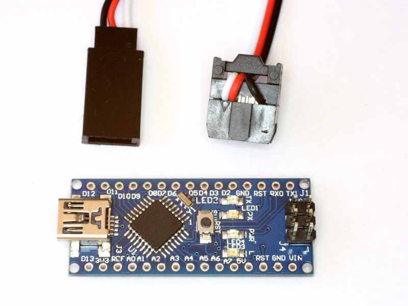
The method used here does not make permanent hardware changes to the Nano. The firmware is compiled in the Arduino workbench and loaded onto the Nano using theUSB FTDI interface. The signal to the ESC is taken from the pin ISP connector using an adapter cable fabricated from a servo extension cable with the female end (meaning with female pins) replaced with a 2x3 IDC header plug.
|
|
Fig 1 shows the standard Nano board with 9 pin ISP header installed, and the adapter cable. Note the IDC header plug picks up the white, red and black wires on pins 1, 2 and 6.
The Nano is powered from the servo cable, and the firmware starts a timer when power is applied to the system, and after a programmable delay starts the up ramp and down ramp.
An eLogger4 was used to capture voltage, current, servo, and rpm.
Another cycle is intiated by repowering the system, which also triggers a new recording session in the eLogger4.
The captured data can be downloaded and analysed.
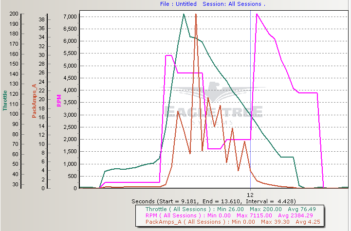 |
Fig 2 shows capture of a drive system where the ESC loses sync with the motor.
Fig 3 is a short video demonstration.
Example code is at Arduino RC servo ramp generator.
Changes should be made as appropriate to create the test signal desired.
| Version | Date | Description |
| 1.01 | 28/08/2013 | Initial. |
| 1.02 | ||
| 1.03 |
© Copyright: Owen Duffy 1995, 2021. All rights reserved. Disclaimer.