 |
| OwenDuffy.net |
|
This article describes another variant of the Simple Morse beacon keyer project. This one is incorporates an A/B RF switch controlled by special characters in the message.
|
|
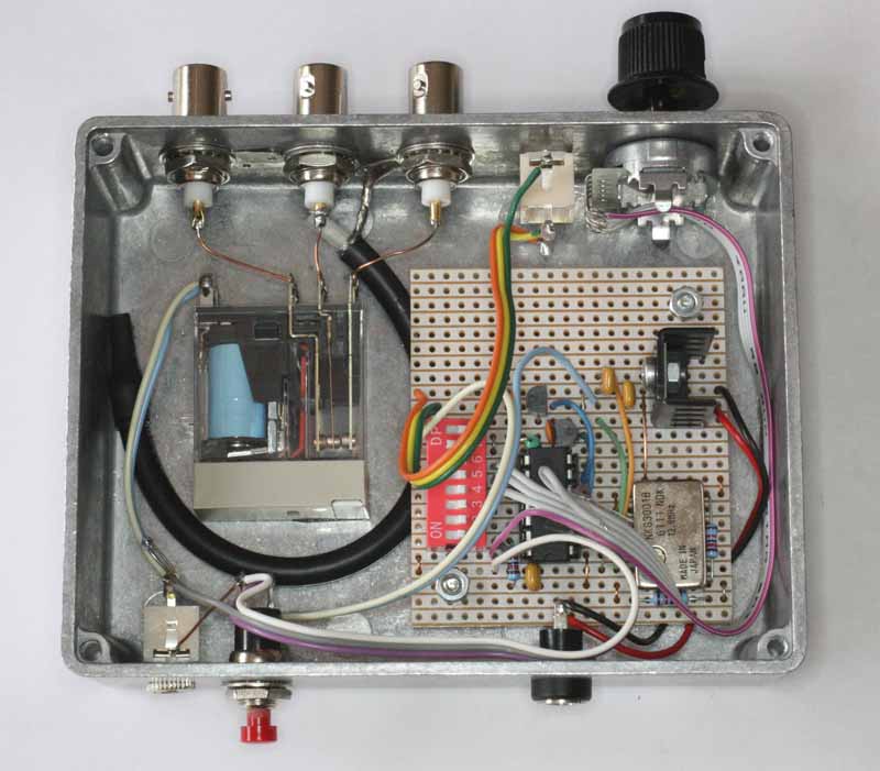
Fig 1 shows the implementation of the keyer using an ATTiny44. This keyer uses a TCXO for more accurate timing, allowing "image stacking" as discussed at QRP QRSS Beacon Transmitter - on air. Experience is that if the keyer keeps time to within 30ms per day, or about 1s per month with moderate temperature variation (10°-40°).
This variant has a set of DIP switches for selecting one of four speeds (12WPM, QRSS1, QRSS6, QRSS15). Most HF grabbers have FFT bandwidth and capture cycle optimised for QRRS6 so it is more or less the standard, though some of people use different things, often at the expense of bandwidth and performance. A later modification added an external multi position switch for message selection.
The three BNC connector are for antenna B, input and antenna A. The coax is an o/c stub for compensation of the relay (High frequency compensation of T/R relay), insertion VSWR is better than 1.03 at 30MHz, better than 1.09 at 60MHz. It is really intended for HF, but at a pinch would work ok on 6m.
On the lower side in the pic there is a DC connector for 12V, and a 3.5mm TRS jack with KEY on the TIP and AUX on the sleeve if routed via the DIP switches.
On the top side in the pic, there is a reset button and a TRS jack for use with ATB - a bootloader for AVR Tiny microcontrollers, Simple Morse beacon keyer - using ATB for more information. ATB allows message replacement (or firmware upgrade) using a simple USB-RS232/TTL adapter, eg the OPC478U adapter and the ATBU utility program.
The internal DIP switches have become largely redundant with the external message select switch and the ability to set speed in the message content. S7 and S8 are used to steer AUX to either the relay or R of the TRS ouput jack.
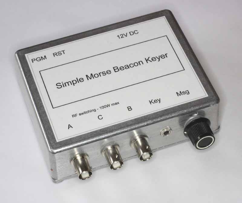 |
Fig 2 shows the finished keyer housed in an inexpensive die cast box with some self adhesive rubber feet to prevent damage to surfaces.
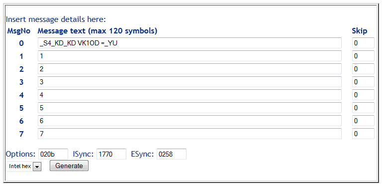 |
Fig 3 shows the message programming with options for 12.8MHz TCXO, inverted message and speed pins, Gray code message selection and 10min cycle timer. The messages in slots 1-7 are test messages to verify Gray code conversion.
| Version | Date | Description |
| 1.01 | 13/12/2012 | Initial. |
| 1.02 | 01/02/2013 | Added external speed switch. |
| 1.03 | ||
| 1.04 | ||
| 1.05 |
© Copyright: Owen Duffy 1995, 2021. All rights reserved. Disclaimer.