 |
| OwenDuffy.net |
|
This article contains notes on installation of a Roger Beep inside a Kenwood MC80 desk microphone.
CAVEAT: Any modifications that you make to your transceiver are entirely your own responsibility. Owen Duffy takes no responsibility for the accuracy of this article, or for the outcome of your modifications. Modification of a transceiver may have implications for original warranty.
The Roger Beep module is powered from the 6V supply on the MC80 PCB, R4 on the Roger Beep needs to be 150Ω rather than the 470Ω supplied in the kit.
|
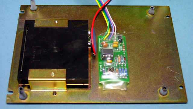
Fig 1 shows Roger Beep module enclosed in heatshrink tube and fixed to baseplate using double sided foam tape. Note the hole cut in the shrink wrap to provide access to the level adjustment pot.
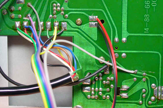 |
Fig 2 shows the connections to the MC80 PCB. The ribbon cable in the foreground from the Roger Beep module is conected as follows:
Adjustment procedure
Before finally tucking the module into the transceiver:
| Version | Date | Description |
| 1.01 | 03/11/2008 | Initial. |
| 1.02 | ||
| 1.03 | ||
| 1.04 |
© Copyright: Owen Duffy 1995, 2021. All rights reserved. Disclaimer.