 |
| OwenDuffy.net |
|
Some GPS receivers output a Pulse Per Second (PPS) signal, being a short duration pulse synchronised to the second. These pulse are often very short, for example 10µs for the Trimble Thunderbolt GPS and too short for some projects.
gpsppsu is a utility that can:
In mode 1, the device will not respond again to triggers until after the completion of an output pulse, ie it is not retriggerable whilst output=1.
The mode is selected within the firmware based on whether or not the internal 8MHz RC clock is enabled. If so, mode 1 is used, otherwise the assumption is that an accurate clock is provided and mode 2 operates.
|
|
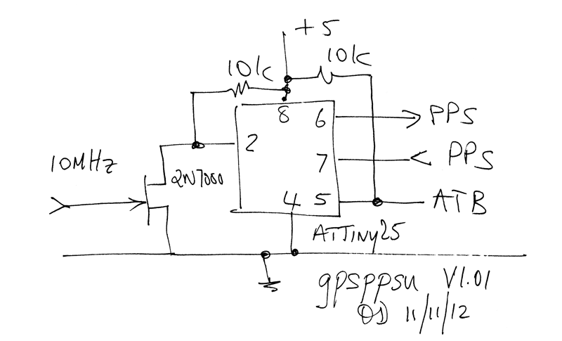
Fig 1 shows the schematic diagram and includes optional parts. For mode 1, the 2N7000 circuitry is not needed. For mode 2, the clock could be provided by a standard crystal oscillator circuit using the ATTiny25 (see its documentation). Another option is a TTL TCXO module on board.
Depending on the lengths of interconnect cables, terminations may be required at the PPSIn and ClockIn interfaces for best performance.
The 10k R and ATB pin wiring is optional, and only required if ATB - a bootloader for AVR Tiny microcontrollers is used.
Calibration data is held in EEPROM.
The duration of mark and space (tm and ts) is given by the following expressions
Note that ts is not used for Mode 1, the timing of the next pulse is determine by a rising edge on PpsIn.
The algorithm allows up to 10s elements with a 10MHz clock, in increments of 1 clock pulse (100ns).
| Offset | Variable | Type | Comments |
| 0 | ver | uint8 | Version |
| 1 | mc1 | uint8 | |
| 2 | mc3 | uint16 | |
| 4 | mnop | uint8 | |
| 5 | sc1 | uint8 | |
| 6 | sc3 | uint16 | |
| 8 | snop | uint8 |
The table above gives the format of the EEPROM image. uint16 values are stored little endian, ie least significant byte at lowest address.
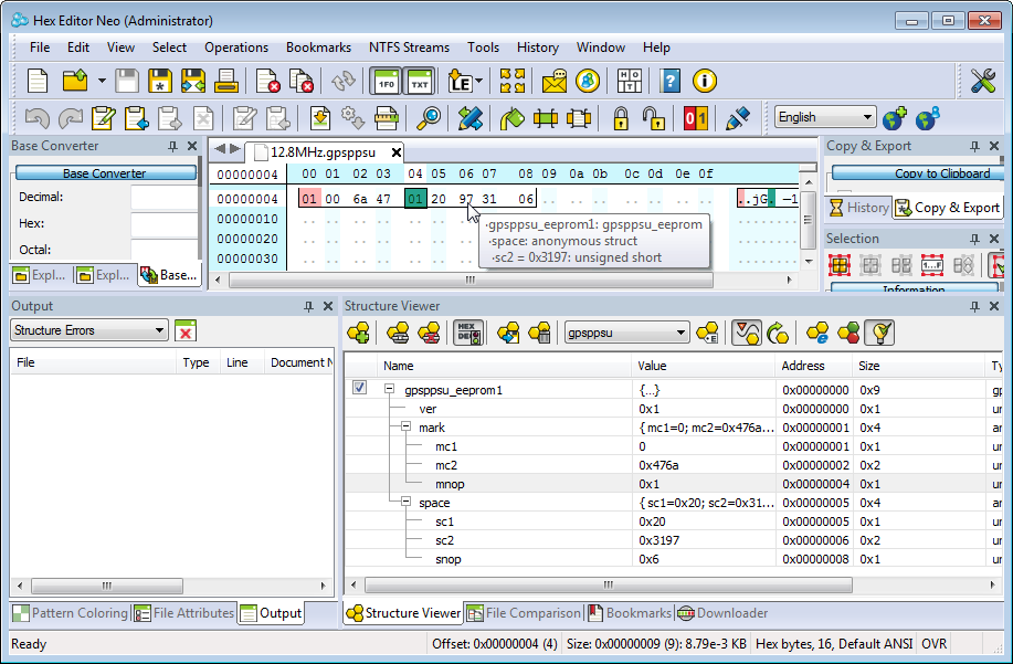 |
Fig 2 shows an example binary format EEPROM data file with the structures expanded in Hex Editor Neo Professional. Note that in Intel hex format, this binary data is wrapped in the Intel formatting.
The spreadsheet gpsppsu.xlsx is a tool for calculating the calibration constants.
Some example hex files for 10ms pulse from various clocks are available below.
The way in which the incoming PPS is sensed leads to jitter of potentially four clock cycles or 500ns. If very low jitter is an application requirement, make a pulse stretcher with a 74HC123.
In mode 2, the device creates an accurate PPS clock with very low jitter, but there is no reference to UTCS so the PPS clock is not synchronised to UTC.
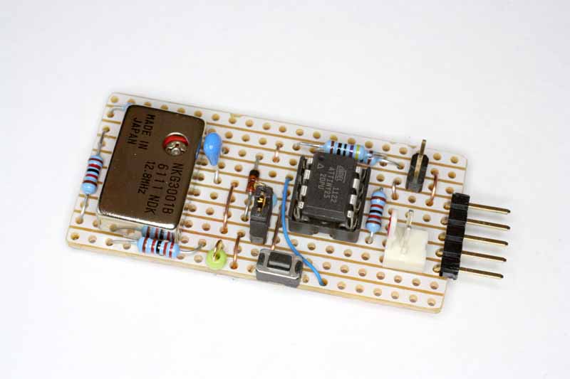 |
Fig 3 shows an implementation of gpsppsu clocked by an inexpensive TCXO (<$5 posted on eBay). The device is a prototype for testing various features, so some of the connectors, test points etc are not needed in a minimal implementation. This one has shunts to allow operation from 10-16V, or 5V directly (shunt in the 12V position, move to the other header for 5V). The white polarised header is a connection for ATB - a bootloader for AVR Tiny microcontrollers.
Pins on the 5 pin connector from the top are Vcc, PPSin,PPSout,ATB,Gnd.
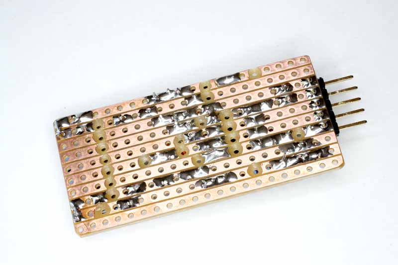 |
Fig 4 shows the underside of the prototype.
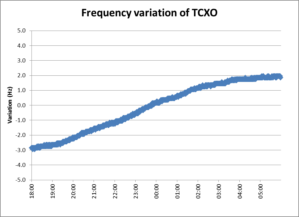 |
Fig 5 shows a plot of frequency variation of the 12.8MHz TCXO measured in about 760 measurements over 12h using a GPSDO reference. During the test, temperature varied from 26.8° to 14.8°, and calculated temperature coefficient of frequency is 0.032ppm/°
| Version | Date | Description |
| 1.01 | 11/11/2012 | Initial. |
| 1.02 | 15/11/2012 | Updated for EEPROM storage of calibration constants. |
| 1.03 | ||
| 1.04 | ||
| 1.05 | ||
| 1.06 |
© Copyright: Owen Duffy 1995, 2021. All rights reserved. Disclaimer.