 |
| OwenDuffy.net |
|
| This article describes the addition of a peak amplifier to a Drake W4 directional wattmeter, to extend the instrument to measure Peak Envelope Power of SSB telephony waveforms. |
The ITU Radio Regulations define the terms Peak Envelope Power, Mean Power and Carrier Power with regard to a radio transmitter. The terms are defined as:
Note: For use in formulae, the symbol p denotes power expressed in watts and the symbol P denotes power expressed in decibels relative to a reference level.
The advantages of a PEP measurement capability are:
| Component | Value |
| R1 | 1,200 |
| R2 | 1,000,000 |
| R5 | 8,200 |
| R6 | 100,000 |
| R9 | 12,000 |
| VR1 | 2,000 |
This amplifier is based on Fig 1 at Peak amplifier for directional wattmeter / SWR meter with values selected to suit the Drake W4, see Table 1 above.
|
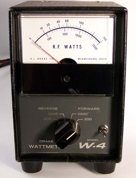
Figure 1 shows the front view of the modified instrument. The miniature toggle switch is an addition and selects normal mode, or peak mode.
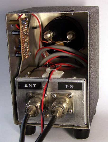 |
Figure 2 shows the rear view of the modified instrument.
The peak amplifier is constructed on a small piece of Veroboard and mounted to the side of the instrument case. A DPDT switch is mounted on the front panel to the right of the range switch, allowing the instrument to be used in its original form and with the peak amplifier inserted.
Note the DC -ve lead connected to the case of the sampler element for single point grounding to avoid ground loops impressing voltage drops in the internal ground circuit when using a shared DC power supply. The red +ve lead terminates on the amplifier board, and has been wound around the sensor cable so that the sensor can still be removed from the indicator box and mounted remotely.
The instrument provides quite steady power readings on SSB telephony. The decay time constant at around 5 seconds is longish, but quite suitable.
The amplifier fulfils its intended purpose.
The instrument was setup with a 100W transmitter for about 70% deflection and the power measured for a continuous carrier at 93W. Single pulses of carrier of duration 27mS were then measured and the meter pointer peaked at 85W, or 91% of the true peak power.
By way of a comparison, a test was performed on a Bird 4314 in PEAK READ mode. The instrument was setup with a 50W transmitter for about 70% deflection and the power measured for a continuous carrier at 50W. Single pulses of carrier of duration 27ms were then measured and the meter pointer peaked at 18W, or 20% of the true peak power. Single pulses of carrier of duration 175ms were required for the meter pointer to peak at 45W, or 90% of the true peak envelope power.
| Carrier PEP | Carrier burst duration | W4 + peak amp | Bird 4314 PEAK READ | ||
| Power | Error | Power | Error | ||
| 50 W | 27 ms | 45W | 10% | 18W | 64% |
| 50 W | 175 ms | 48W | 4% | 45W | 10% |
The decay time constant of the Bird 4314 is just under 2 seconds, whereas the W4 is around 5 seconds.
© Copyright: Owen Duffy 1995, 2021. All rights reserved. Disclaimer.