 |
| OwenDuffy.net |
|
This tutorial shows how to explore an inexpensive DS1307 Real Time Clock module with Arduino using the DS1307RTC and Time libraries.
The RTC module can be purchased on eBay at very low cost (<$3), and is an ideal educational project for the budding Arduino practitioner.
It is an ideal low cost project for a first exploration of explore I2C.
|
|
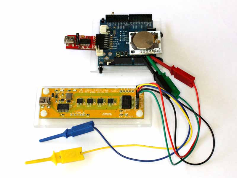
Fig 1 shows the test setup:
A 5 way male header pin strip was soldered to the RTC module, pins down, so that it can plug into the Arduino board. The RTC module is plugged in so that the left hand four pins engage the right hand four pins of the Arduino, there will be one RTC module pin to the right of the Arduino header socket not connected. This alignment is important, it aligns the SCK, SDA, Vcc and Gnd pins with Arduino pins a0, a1, a2, a3.
The project uses the DS1307RTC and Time library modules in Arduino, and the v1.05 Arduino IDE is used for the project. The DS1307RTC library package contains example code to set and read the RTC, they are used here with small modification. Arduino libraries do not maintain backwards compatibility and this code may not run in earlier versions.
The source code is modified in both examples to put Vcc and Gnd on a3 and a2 to power the RTC module (without using jumper leads).
#include <Time.h>
#include <DS1307RTC.h>
#include <Wire.h>

#define OFFSET 15

const char *monthName[12] = {
"Jan", "Feb", "Mar", "Apr", "May", "Jun",
"Jul", "Aug", "Sep", "Oct", "Nov", "Dec"
};

tmElements_t tm;

void setup() {
bool parse=false;
bool config=false;

//setup VCC and GND on a3, a2
pinMode(16,OUTPUT);
digitalWrite(16,LOW);
pinMode(17,OUTPUT);
digitalWrite(17,HIGH);

// get the date and time the compiler was run
if (getDate(__DATE__) && getTime(__TIME__)) {
parse = true;
// and configure the RTC with this info
if (RTC.write(tm)) {
if(RTC.set(RTC.get()+OFFSET)){
config = true;
}
}
}

Serial.begin(9600);
while (!Serial) ; // wait for Arduino Serial Monitor
delay(200);
if (parse && config) {
Serial.print("DS1307 configured Time=");
Serial.print(__TIME__);
Serial.print(", Date=");
Serial.println(__DATE__);
} else if (parse) {
Serial.println("DS1307 Communication Error :-{");
Serial.println("Please check your circuitry");
} else {
Serial.print("Could not parse info from the compiler, Time=\"");
Serial.print(__TIME__);
Serial.print("\", Date=\"");
Serial.print(__DATE__);
Serial.println("\"");
}
}
|
Fig 2 shows the modified example sketch for setting the time. The OFFSET macro and realted calculation is a further modification to allow for the offset between the time the sketch is compiled and when it executes on the Arduino.
void loop() {
}

bool getTime(const char *str)
{
int Hour, Min, Sec;

if (sscanf(str, "%d:%d:%d", &Hour, &Min, &Sec) != 3) return false;
tm.Hour = Hour;
tm.Minute = Min;
tm.Second = Sec;
return true;
}

bool getDate(const char *str)
{
char Month[12];
int Day, Year;
uint8_t monthIndex;

if (sscanf(str, "%s %d %d", Month, &Day, &Year) != 3) return false;
for (monthIndex = 0; monthIndex < 12; monthIndex++) {
if (strcmp(Month, monthName[monthIndex]) == 0) break;
}
if (monthIndex >= 12) return false;
tm.Day = Day;
tm.Month = monthIndex + 1;
tm.Year = CalendarYrToTm(Year);
return true;
}

#include <Time.h>
#include <DS1307RTC.h>
#include <Wire.h>

void setup() {
//setup VCC and GND on a3, a2
pinMode(16,OUTPUT);
digitalWrite(16,LOW);
pinMode(17,OUTPUT);
digitalWrite(17,HIGH);

Serial.begin(9600);
while (!Serial) ; // wait for serial
delay(200);
Serial.println("DS1307RTC Read Test");
Serial.println("-------------------");
}

void loop() {
tmElements_t tm;

if (RTC.read(tm)) {
Serial.print("Ok, Time = ");
print2digits(tm.Hour);
Serial.write(':');
print2digits(tm.Minute);
Serial.write(':');
print2digits(tm.Second);
Serial.print(", Date (D/M/Y) = ");
Serial.print(tm.Day);
Serial.write('/');
Serial.print(tm.Month);
Serial.write('/');
Serial.print(tmYearToCalendar(tm.Year));
Serial.println();
} else {
if (RTC.chipPresent()) {
Serial.println("The DS1307 is stopped. Please run the SetTime");
Serial.println("example to initialize the time and begin running.");
Serial.println();
} else {
Serial.println("DS1307 read error! Please check the circuitry.");
Serial.println();
}
delay(9000);
}
delay(1000);
}

void print2digits(int number) {
if (number >= 0 && number < 10) {
Serial.write('0');
}
Serial.print(number);
}
|
Fig 3 shows the modified read sketch.
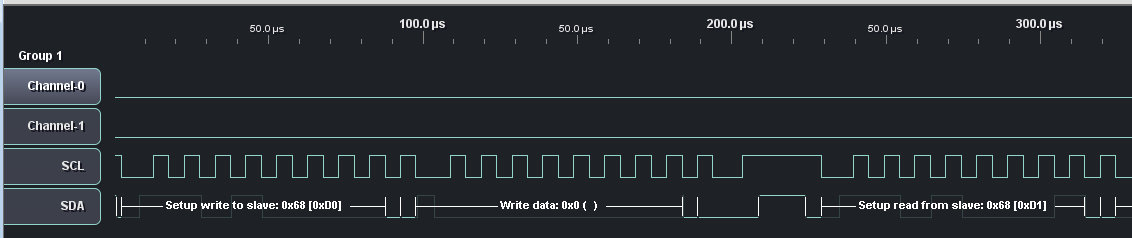 |
Fig 4 shows the waveforms captured on the SCL and SDA pins, the I2C transaction to read the clock. Only the first bytes of the transaction are shown.
|
Fig 5 shows an analysis of the complete read transaction.
The student of I2C should be able to take the DS1307 data sheet and the dump in Fig 5 and verify the reading process and determine the time and date read in the transaction (hint: is is around the date that this article was written).
| Version | Date | Description |
| 1.01 | 07/12/2013 | Initial. |
| 1.02 | ||
| 1.03 | ||
| 1.04 | ||
| 1.05 |
© Copyright: Owen Duffy 1995, 2021. All rights reserved. Disclaimer.