Measuring SSB transmitter power
RF Power terms
The ITU Radio Regulations define the terms Peak Envelope Power, Mean Power and Carrier Power with regard to a radio transmitter. The terms are defined as:
- Peak Envelope Power 'pX' (s1.157) means the average power supplied to the antenna transmission line by a transmitter during one radiofrequency cycle at the crest of the modulation envelope taken under normal operating conditions.
- Mean Power 'pY' (s1.158) means the average power supplied to the antenna transmission line by a transmitter during an interval of time sufficiently long compared with the lowest frequency encountered in the modulation taken under normal operating conditions.
- Carrier Power 'pZ' (s1.159) means the average power supplied to the antenna transmission line by a transmitter during one radio frequency cycle taken under the condition of no modulation.
Note: For use in formulae, the symbol p denotes power expressed in watts and the symbol P denotes power expressed in decibels relative to a reference level.
PEP RF output power measurement
PEP can be measured and displayed on a conventional directional wattmeter extended with a peak hold amplifier. It is a more effective and more accurate method of measuring PEP on speech than using a non storage oscilloscope where the user may miss some peaks.
The advantages of a PEP measurement capability are:
- convenient and accurate measurement of PEP (ITU pX) output power (eg for licence compliance, adjustment of amplifier drive level);
- more effective monitoring of antenna system health as intermittent faults conditions will be better captured by the peak detector and result in more noticeable deflection in the reverse metering position.
Note that there are power meters sold that have switches labelled PEP, but many do not provide accurate PEP readings on speech. The user needs to validate claimed PEP measurement capability.
Example RF output power measurements
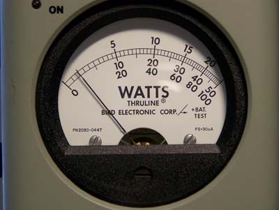
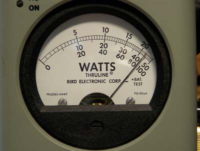
100W PEP transceiver - speech processor OFF
The test scenario:
|
|
| Bird 4314 - Normal mode | Bird 4314 - PEAK READ mode |
 |
 |
|
The measured PEP is more than 20 times the power indicated by the meter with PEAK READ off. |
|
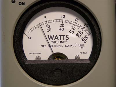
100W PEP transceiver - speech processor ON
The test scenario:
|
|
| Bird 4314 - Normal mode | Bird 4314 - PEAK READ mode |
 |
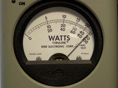 |
| Conclusion:
The measured PEP is more than 7 times the power indicated by the meter with PEAK READ off. |
|
700W PEP transmitter - speech processor ON
The test scenario:
|
|
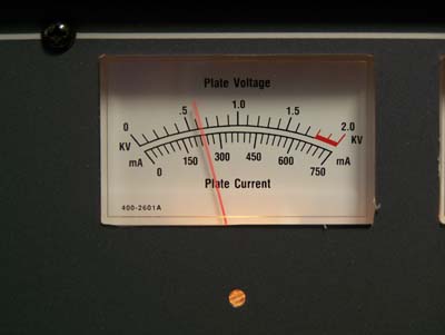
| AL-811H plate current | Bird 4314 - PEAK READ mode |
 |
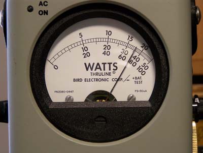 |
| The plate to cathode voltage of the PA is about 1800 volts. The plate current meter indicates 230mA, which suggests a power input of 414W. | RF power output is 700WpX (PEP). |
| Conclusion: the PA DC instrumentation is of little value in determining PEP output on speech. | |
Typical power meter response
A typical RF directional power meter uses a half wave rectifier with capacitor input filter to convert a sample of the RF power to a DC voltage.
The capacitor charges to almost the peak voltage of the RF waveform and discharges. The DC voltage is proportional to the square root of RF power.
The DC output is not constant, it varies with the RF waveform because the filter discharge time is short relative to the variation in power with speech. So, the "DC" voltage is varying in sympathy with the speech.
This time varying "DC" voltage is fed to a d'arsonval movement (moving coil) meter which deflects according to the average torque or current.
So the meter deflection is the average of the square root of power, and the time constant of the rectifier filter and ballistics of meters varies from instrument to instrument. There is no reason to think that such a meter indicates "Average Power" or "Mean Power".
These instruments are calibrated on a steady (unmodulated) carrier, and are only accurate on such a waveform.
In a simple test, the output of an A1 Morse Code transmitter was measured with a Drake W4 directional wattmeter "key down" at 100W. The transmitter was then keyed with a automatically generated continuous stream of dits which have a duty cycle of 50% for an average power of 50W. The wattmeter indicated 28W for the 50% duty cycle stream, the meter does not read "Average Power" or "Mean Power" on an amplitude modulated carrier.
Conclusions
- PEP can be measured and displayed on a conventional directional wattmeter extended with a peak hold amplifier;
- with speech processing OFF, the measured PEP in this test is more than 20 times the power indicated by the meter with PEAK READ off;
- with speech processing ON, the measured PEP in this test is more than 7 times the power indicated by the meter with PEAK READ off;
- PA DC instrumentation is of little value in determining PEP output on speech; and
- typical directional wattmeters are not "average reading" (in terms of ITU-R pY or Mean Power).
Unless a transceiver incorporates a properly calibrated power control that truly controls PEP output power, there is little confidence that the operator can adjust the transceiver for any specific level of PEP below the rated maximum unless they use a PEP wattmeter. The first test above shows that if an operator "talks up" to 10W on a Bird 43 wattmeter, they could be running around 200W PEP (if the transceiver is capable of that).
Links
Changes
| Version | Date | Description |
| 1.01 | 05/06/2007 | Initial. |
| 1.02 | ||
| 1.03 |