Another RFI mod of a speaker mic for DMR use

I bought a remote speaker-microphone (RSM) for a DMR portable from eBay (~$12 posted). Experience says that these suffer RF ingress which is seriously bad in DMR due to the amplitude modulation of the transmitted signal.

This RSM had somewhat improved filtering around the electret compared to others I have purchased. Continue reading Another RFI mod of a speaker mic for DMR use

80m voltage fed Half Square matching workup

A correspondent wrote asking about the design of a matching network for a Half Square antenna for 80m, voltage fed at one end.

Above is the current distribution on the half square voltage fed. It is essentially two in-phase vertical quarter waves separated a half wavelength, a broadside array.

Feed point impedance at resonance is very high 5700Ω, and being a high Q antenna, they are very sensitive to dimensions, nearby clutter etc. Note that this is calculated for an antenna in the clear, it will be different where trees or conductive mast exist nearby. Continue reading 80m voltage fed Half Square matching workup

Surecom SW-102 VSWR meter review – v2.6

At Surecom SW-102 VSWR meter review I wrote a review of a meter which I had purchased a little over a year ago, it was at v4.5.

One of the many problems identified was inconsistency of displayed values.

v2.6

Surecom’s versions are confusing, the highest number is not necessarily the latest version. It appears a partial version history from their current page advertising the SW-102 is:

OLD VERSION : V3.3 ,V3.8 ,V4.5,V4.9 ,V5.0,V5.1
2017-8 NEW VERSION : V2.02 ,V2.03

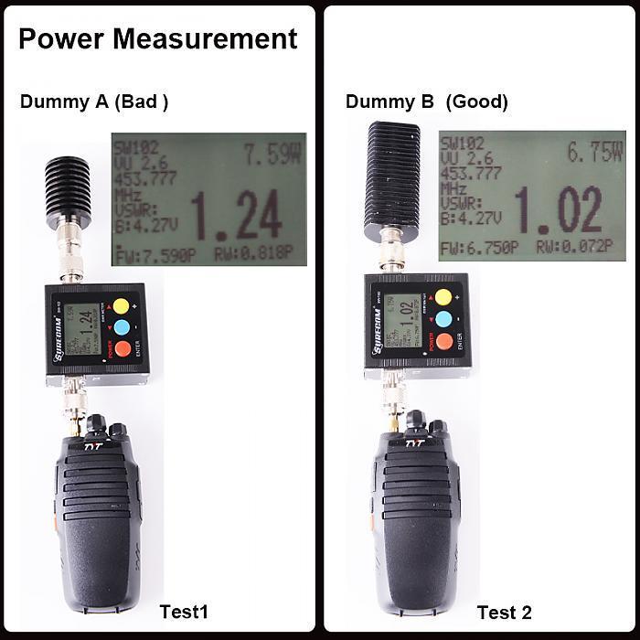
The following image is from Surecom’s current page advertising the SW-102, and I assume that the version shown here (v2.6) is the latest at time of writing.

The image captures the outputs of two tests with poor and good dummy loads.

Let’s check the displayed values for internal consistency. Continue reading Surecom SW-102 VSWR meter review – v2.6

An RF choke for a 1.8-30MHz coax power injector – LF1260 core

This article describes a prototype RF choke (RFC) for use in a power injector for 50Ω coax over range 1.8-30MHz. Power injector / extractors are often used to connect power and / or signalling on a shared common RF coax feed line to accessories such as remote antenna switches and ATUs.

Design criteria are:

  • Insertion VSWR of the RFC in shunt with 50+j0Ω < 1.1;
  • Dissipation < 2% of a 100W transmitter.

The core chose is a LF1260 ferrite suppression bead from Jaycar. It is a medium / high µ core readily available in Australia at $7.50 / 6.


Above is the prototype RFC wound with data cable wire for the purpose of measurement. In application it could be wound with 1mm enamelled copper or PTFE insulated wire (Curie point is lowish at 120°+, but it still benefits from higher temperature insulation). Continue reading An RF choke for a 1.8-30MHz coax power injector – LF1260 core

Line loss under standing waves – recommendation of dodgy tool on eHam

In a discussion about using a 40m centre fed half wave dipole on 80m, the matter of feed line loss came up and online expert KM1H offered:

Use this to help make up your mind. Add it to the normal coax loss. http://www.csgnetwork.com/vswrlosscalc.html

This is to suggest that the feed line loss under standing waves can be calculated with that calculator.

He then berates and demeans a participant for commenting on his recommendation, bluster is par for the course in these venues.

Calculator analysis

The calculator in question states this calculator is designed to give the efficiency loss of a given antenna, based on the input of VSWR (voltage standing wave ratio) and other subsequent factors.

This is a bit wishy washy, efficiency loss is not very clear. The usual meaning of efficiency is PowerOut/PowerIn, and the usual meaning of loss is PowerIn/PowerOut, both can be expresssed in dB: LossdB=10*log(Loss) and EfficiencydB=10*log(Efficiency). Continue reading Line loss under standing waves – recommendation of dodgy tool on eHam

G3CWI’s ground wave tests Jul 2017 using WSPRlite

Richard (G3CWI) published an interesting blog article Comparison of groundwave performance of Small Transmitting Loop and Quarterwave GP summarising a recent WSPR test on 40m over 20km distance.

This article is a walk through of the expected WSPR receive S/N for the case of the 20mW tx on a quarter wave vertical.

100% efficient tx and rx antenna systems

Ground wave suffers attenuation due to two key components:

  1. dispersion of energy as the wave spreads out from the source; and
  2. absorption of energy in heating the soil.

Item (1) is simply inverse square law effect, and Norton provides us with several approximations for estimating (2) from Sommerfields work.

Calculate efficiency of vertically polarised antenna from far field strength uses Norton’s f5 approximation for ground wave attenuation.

Above is a calculation for a 100% efficient transmitter. (The trick to getting this is to leave the measured field strength field empty and the calculator will insert the value that gives 100% efficiency.)

So the next question is what ambient noise level might we expect in a rural setting on 40m. Continue reading G3CWI’s ground wave tests Jul 2017 using WSPRlite

Exploiting your antenna analyser #29

Resolving the sign of reactance – a method – Smith chart detail

Exploiting your antenna analyser #28 gave an example of use of one method to resolve the sign of reactance comparing measurements made with a slightly longer known transmission line.

One way to predict the input impedance to the longer line is using a Smith chart. This article presents a Smith chart prediction of the expected input impedance of a 8′ section of RG8 at 14.17Mhz (vf=0.66, length=0.175λ) for the cases of Zload being 60.3+j26.9Ω and  60.3-j26.9Ω.

60.3+j26.9Ω

The impedance is normalised to 50Ω and plotted on the Smith chart, point 1 above. A radial from the centre through point 1 is drawn to the edge of the chart. Another radial is drawn a distance towards the generator of 0.175λ and using a pair of dividers or ruler, point 2 is plotted on that radial at the same distance from the centre (same VSWR) as point 1.

These points are on a constant VSWR arc but the arc has not been draw because the two arcs would overlap and might be confusing to some readers.  Continue reading Exploiting your antenna analyser #29

Exploiting your antenna analyser #28

Resolving the sign of reactance – a method

Many analysers do not measure the sign of reactance, and display the magnitude of reactance, and likewise for magnitude of phase and magnitude of impedance… though they are often incorrectly and misleadingly labelled otherwise.

The article The sign of reactance explains the problem and dismisses common recipes for resolving the sign of reactance as not general and not reliable.

This article gives an example of one method that may be useful for resolving the sign of reactance.

My correspondent has measured VSWR=1.68 and |Z|=66 and needs to know R and X. From those values we can calculate R=60.3 and |X|=26.9.

Method

The method involves adding a short series section of known line, short enough to provide a measurement difference in R, and that R would be different for the case of =ve and -ve X, all of these measured at the same frequency. Continue reading Exploiting your antenna analyser #28

A check load for antenna analysers with UHF series socket

Hams embrace the UHF series connectors like no one else, including for its use on test equipment where its performance is lacking.

This is the likely reason why it is so hard to find low VSWR 50Ω terminations with UHF series plug. It is rare to find something with VSWR quoted in specifications, and nigh on impossible to find one at a reasonably low price.

On the other hand, SMA terminations start at about $2 each (posted), and it is not too hard to find ones specified with VSWR<1.2 to several GHz.

Above is a low cost, low quality solution. It is a SMA termination selected from a bunch using a high accuracy DMM (selected, R is 49.86Ω) and a SMA(F)-UHF(M) adapter, total cost $7 (posted) (but you might be advised to buy 5 loads to select the best one). Despite the specification, they are probably only good to 100MHz, and can be unreliable. Continue reading A check load for antenna analysers with UHF series socket

Measuring SSB telephony Peak Envelope Power

Measuring SSB transmitter power has been surrounded in some mystique since the deployment of such transmitters in the Amateur service. Some oft cited wisdom includes:

  • Peak Envelope Power (PEP) can only be measured with a two tone waveform;
  • PEP can only be measured with an oscilloscope;
  • PEP of an unmodulated sine wave is twice the average power;
  • PEP is meaningless for anything but SSB.

Lets firstly look at what PEP means in the real world.  Continue reading Measuring SSB telephony Peak Envelope Power