G3CWI 2018 measurements of an Alexloop Walkham

Richard, G3CWI, measured the impedance and bandwidth of a Alexloop Walkham, a popular small transmitting loop (STL). The antenna was situated in the clear at 1.65m centre height above natural ground.

The key measurements were:

  • centre frequency 7.014MHz, |Z|=51Ω, VSWR=1.1;
  • VSWR=3 bandwidth 16.2kHz.

The step size of the analyser prevented measurement exactly at resonance, but R changes very closely with frequency near resonance so we can estimate it quite well. The above figures can be used to find R close to resonance.

Within the limits of measurement error, we can say that R at resonance should be very close to 51Ω, and VSWRmin close to 1.02. Continue reading G3CWI 2018 measurements of an Alexloop Walkham

Findling & Siwiak 2012 measurements of an Alexloop

(Findling, A & Siwiak 2012) documented measurements they made of a popular small transmitting loop (STL), an Alexloop Walkham.

Now Alexloops seem to have undergone some evolution, and there does not seem to be a clear list of model names or numbers with features or specifications, so to some extent the antenna is a little non descript.

The article did not document the environment of the test antenna, but Findling explained in correspondence that it was relatively clear of conducting structures and about 1.2m above natural ground.

A NEC-4.2 model of the antenna at 7MHz was built and calibrated to their measured half power bandwidth (19kHz). Model assumptions include:

  • ‘average’ ground (σ=0.005, εr=13);
  • Q of the tuning capacitor = 1000;
  • conductivity of the loop conductor adjusted to calibrate the model half power bandwidth to measurement.

Note that the model may depart from the actual test scenario in other ways, it is challenging to glean all the data that one would like from the article.

Above is an extract from (Findling, A & Siwiak 2012).

Above is the VSWR scan of the calibrated model, the load is matched at centre frequency and half power bandwidth is taken as the range between ReturnLoss=6.99dB points. Continue reading Findling & Siwiak 2012 measurements of an Alexloop

Single turn coaxial loop resonator analysis

Recent discussion online of a purported commercial HF small transmitting loop (STL) was challenged in analysing the structure, questioning whether such a connection was ‘correct’.

The STL used a main loop resonator and a separate small auxiliary loop for the 50Ω feed, a very common arrangement.

The main loop is a coaxial cable with, in this case, a tuning capacitor inserted between the inner conductors at each end. Above is a diagram of the main loop. Continue reading Single turn coaxial loop resonator analysis

WW1WW’s matching transformer for an EFHW

At PD7MAA’s BN43-202 matching transformer for an EFHW I gave an estimate of the core loss in PD7MAA’s transformer.

An online expert questioned the analysis and later measurements, and proposed his own transformer design as evidence.

Notably, his transformer uses #61 material and a larger binocular core, a Fair-rite 2861006802 with 2t for a nominal 50Ω primary, giving loss measurements at 7MHz of 0.08dB. Note that the confidence limits of that loss measurement because of the way in which it was obtained (eg a 1% error in the 1120Ω load resistor contributes 0.043dB error to the result), but the measurements do suggest that the loss is probably very low.

Though the loss is low and Return Loss is high at 7MHz, the limits for ReturnLoss>14dB (VSWR<1.5) is 5-18MHz. With compensation, that range may be changed.

Prediction

Lets apply the method laid out at PD7MAA’s BN43-202 matching transformer for an EFHW.

The best Fair-rite data I can find quickly is a chart of the impedance of a one turn winding.

Scaling from this graph, Xs is close of 35Ω at 7MHz, so lets used that to derive some basic parameters for the core. Continue reading WW1WW’s matching transformer for an EFHW

AIM 914 produces internally inconsistent results


AIMuhf

A new release, AIM914 appeared recently.

In the common theme of one step forward, two steps backwards, this version has defects that were not present in AIM910B.

Let’s review the internal consistency of this part of the display screen.

Most of the values given above are calculated from a single measurement value, and should be internally consistent. That measurement value is translated to different quantities, many based on the stated Zref (75Ω in this case). Continue reading AIM 914 produces internally inconsistent results

Matched Line Loss of generic RG6/U Quad Shield CCS

This article documents a measurement of Matched Line Loss (MLL) of a 35m test section of generic RG6/U Quad Shield CCS.

It has become impossible in recent years to buy low cost RG6/U with solid centre conductor locally, and the imported product with solid copper conductor is prohibitively expensive (~$6/m as against $0.35/m for the CCS).

The CCS cable does have near copper like performance at UHF and above, but what is its behavior at HF?

Above is calculated MLL from a S11 scan of the test section with S/C and O/C termination. There is a little ripple on the response due to measurement error. The graph also has a curve fit, MLL=0.0285f^0.1506 (F in MHz). Continue reading Matched Line Loss of generic RG6/U Quad Shield CCS

KN5L measurement of JSC 1318 windowed ladder line – MLL @ 4.2MHz

John, KN5L, published some interesting measurements he made of a recent purchase of JSC 1318 windowed ladder line. JSC Wire & Cable is now known as Seminole Wire & Cable, and this is their 1318 product.

Product with apparently similar specifications are sold by many ham retailers, they may or may not be sourced from Seminole.

Some sellers specify the % IACS rating of the copper clad conductor, usually 30%, some just don’t mention it.

John carefully measured the DC resistance of his line section, and found that it reconciled well with the Copperweld datasheet for 21% CCS.

He also used a VNA to measure S11 of the line section with S/C and O/C terminations, and he gives links to the Touchstone files at the top of his page.

The O/C Touchstone file allows calculation of Zin. The O/C line exhibits resonance at 4.2MHz, at Zin=3.7Ω. His fuller set of measurements showed that Zo at 4.2MHz is very close to 400Ω. We can use those measurements to calculate Matched Line Loss (MLL).

Above, MLL is 0.50852dB/100m.
Continue reading KN5L measurement of JSC 1318 windowed ladder line – MLL @ 4.2MHz

Transmission line measurements – learning from failure

Introduction

A recent article questioned the accuracy of measurement of Matched Line Loss (MLL) for a modified commercial transmission line. The published results were less than half the loss of an equivalent line in air using copper conductors and lossless dielectric, when in fact there would be good reason to expect that the line modification would probably increase loss.

How do you avoid the pitfalls of using analysers and VNAs to measure line loss?

Lets walk through a simple exercise that you can try at home with a good one port analyser (or VNA). Measuring something that is totally unknown does not provide an external reference point for judging the reasonableness of the results, so will use something that is known to a fair extent,

Experiment

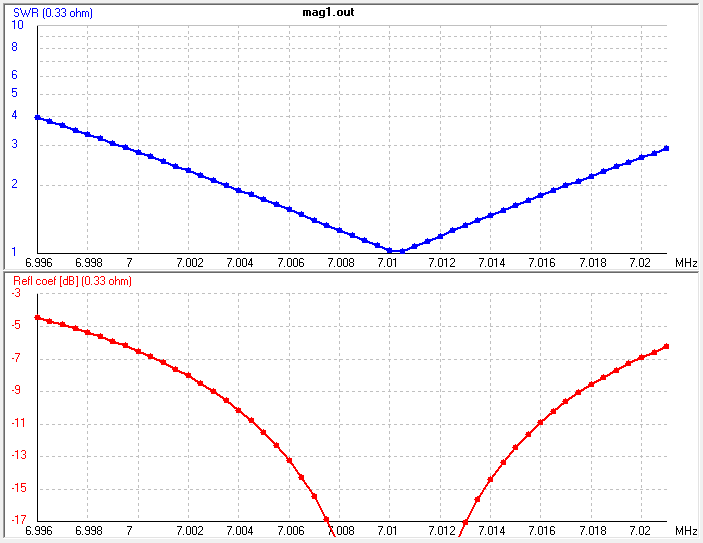
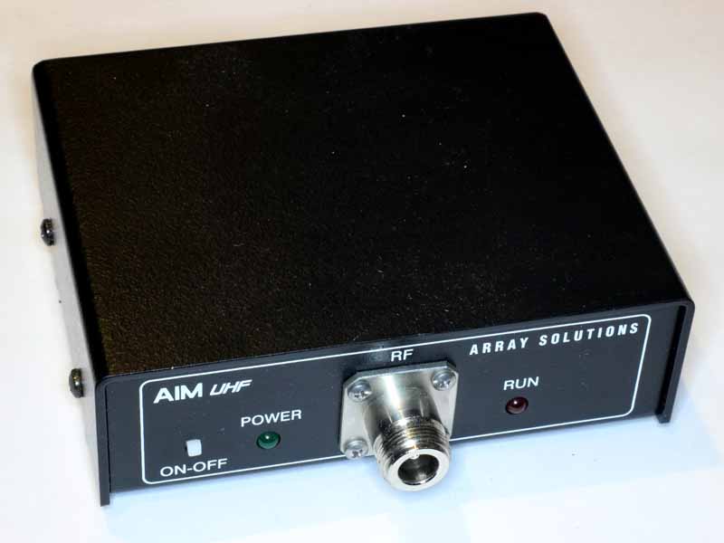
For this exercise, we will measure the Matched Line Loss (MLL) of a 6m length of uniform transmission line, RG58C/U cable, using an AIMUHF analyser. The AIM manual describes the method.

If you need to know the cable loss at other frequencies, enable the Return Loss display using the Setup menu and click Plot Parameters -> Return Loss and then do a regular scan of the cable over the desired frequency range with the far end of the cable open. Move the blue vertical cursor along the scan and the cable loss will be displayed on the right side of the graph for each frequency point

Note the one-way cable loss is numerically equal to one-half of the return loss. The return loss is the loss that the signal experiences in two passes, down and back along the open cable.

Our measurements will show that this is a naively simple explanation, and to take it literally as complete may lead to serious errors. Yes, it IS the equipment manual, but it is my experience that the designers of equipment, and writers of the manuals often show only a superficial knowledge of the relevant material.
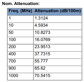
Datasheet

Above is an extract of the datasheet for Belden 8262 RG58C/U type cable, our test cable should have similar characteristics. Continue reading Transmission line measurements – learning from failure

Cheap Chinese wristwatch #1

I bought an inexpensive Chinese manual wind wristwatch for my grandson. It is a skeleton style watch based on the communist Tongji movement.

Above, the watch looking pretty flashy in gold coloured finish. The gold plate wore off the band in just a few days to reveal a brass band tarnishing by the hour. The bezel is probably base metal and will corrode in no time. Continue reading Cheap Chinese wristwatch #1