Finding velocity factor of coaxial transmission line – a challenge

An upcoming article works through an approach to finding the velocity factor of a sample of coaxial cable using an antenna analyser.

As a precursor, this article poses a challenge that will identify the issues relevant to the problem.

Case 1:

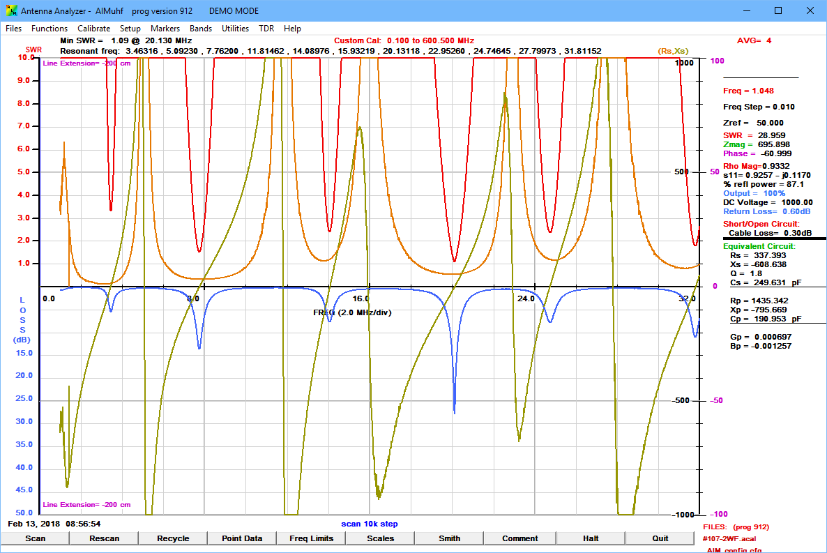
A Rigexpert has been used to measure the first quarter wave resonance of a length of ‘unknown’ semi air dielectric RG6.

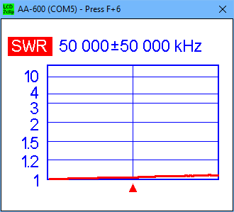
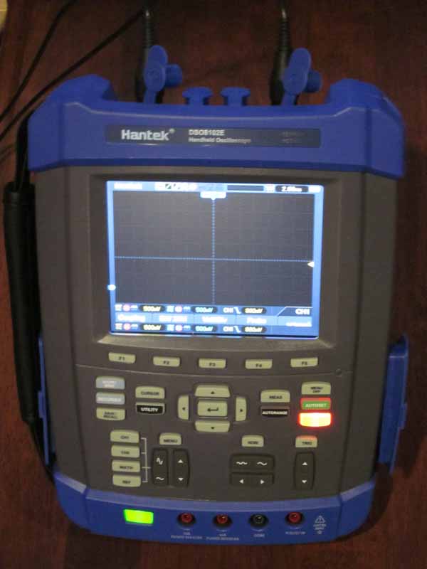
The length of RG6 Dual Shield is terminated in an F connectors at one end, the other end cut cleanly square. It is connected via  N(M)-BNC(F) and BNC(M)-F(F) adapters to a Rigexpert AA-600 antenna analyser and the quarter wave resonance noted (ie the lowest frequency at which measured X passes through zero).

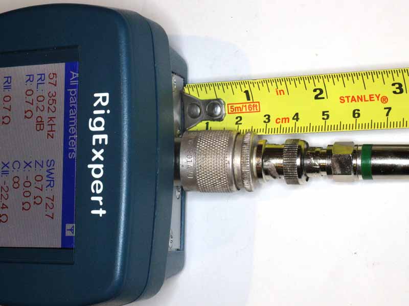
Above, the line section is connected to the Rigexpert via adapters, and the length overall is measured from the case of the AA-600 to the of the cable. The measured length is 1.077m, make any adjustment to that length that you think is justified on the information presented here.
Continue reading Finding velocity factor of coaxial transmission line – a challenge

AIM system – AIM912 initial checkout

Given that most versions of the AIM software that I have tried have had serious defects, I approach the latest release, AIM912, with caution.

An interesting opportunity presented when a correspondent sent me some .scn files captured from an AIM4170B using AIM912.

Above is the correspondents .scn file opened in AIM912. Continue reading AIM system – AIM912 initial checkout

On winding configuration of EFHW matching transformers

The net abounds with articles on broadband transformers (ie untuned) for matching End Fed Half Wave (EFHW) antennas to 50Ω. One of the aspects that is common to most designs is that the turns of the primary winding are wound ‘bifilar’ with the start of the secondary winding, indeed the twist pitch is often very short and articles often go into detail on how to make this magic thing.

The magic is that it is supposed to give closer to ideal behaviour of the transformers by way of minimising flux leakage.

The transformer above is styled on the common design, and it consists of a 2t primary and 16t secondary where the primary is wound bifilar, and a third 2t winding wound over the primary end of the transformer between the other turns. Continue reading On winding configuration of EFHW matching transformers

Ellington 3 x FT240-52 matching transformer for an EFHW

Ellington describes in a Youtube video his high power matching transformer for an EFHW, he rates it suited to 500W CW.

Like almost all such ‘designs’, they are published without supporting measurements or simulations.

The transformer is intended to be used with a load such that the input impedance Zin is approximately 50+j0Ω, Gin=0.02S.

Analysis of a simple model of the transformer with a load such that input impedance is 50+j0Ω gives insight into likely core losses.
Continue reading Ellington 3 x FT240-52 matching transformer for an EFHW

A low cost 50Ω termination for measurement purposes

This article shows just how easy it is to make an inexpensive low VSWR load for antenna analyser validation / measurements.

Above is an AA-600 sweep of the prototype from 10kHz to 100MHz. VSWR reads 1.02 in ‘All’ mode at 100MHz… better than the inherent accuracy of the instrument.

How expensive?

It is made from two 100Ω 1% 1206 SM resistors purchased on eBay for about $2/100, so about $0.04 for the resistors, and 40mm of bare copper wire (0.5mm phone / data wire in this case).

In use, it is held in contact with the coax socket (in this case an N type) with a pair of disposable plastic first aid tweezers (yep, you can buy them on ebay for about $0.20/pair).

While you are at it, make a good short circuit termination by scrunching up a bit of (clean) kitchen aluminium foil and press that against the coax socket conductors.

Try both of these on your antenna analyser and see how it stacks up.

Review of Hantek DSO8102E hand held oscilloscope

This article is a brief review of some issues that were found with initial testing of a Hantek DSO8102E two channel 100MHz hand held oscilloscope.

The DSO8102E is a member of the DSO8000 series (DSO8060, DSO8070E, DSO8100E, DSO8150E, DSO8200E), and shares most specifications across the series.

The specifications are very impressive, and price at just under $1000 for a Chinese brand seemed reasonable (hand held oscilloscopes are expensive compared to bench oscilloscopes).

The test scenario was a practical application, observation of the data traffic to/from a DHT22 temperature and humidity sensor in the project ESP8266 IoT DHT22 temperature and humidity – evolution 2. Continue reading Review of Hantek DSO8102E hand held oscilloscope

Exploiting your antenna analyser #29

Resolving the sign of reactance – a method – Smith chart detail

Exploiting your antenna analyser #28 gave an example of use of one method to resolve the sign of reactance comparing measurements made with a slightly longer known transmission line.

One way to predict the input impedance to the longer line is using a Smith chart. This article presents a Smith chart prediction of the expected input impedance of a 8′ section of RG8 at 14.17Mhz (vf=0.66, length=0.175λ) for the cases of Zload being 60.3+j26.9Ω and  60.3-j26.9Ω.

60.3+j26.9Ω

The impedance is normalised to 50Ω and plotted on the Smith chart, point 1 above. A radial from the centre through point 1 is drawn to the edge of the chart. Another radial is drawn a distance towards the generator of 0.175λ and using a pair of dividers or ruler, point 2 is plotted on that radial at the same distance from the centre (same VSWR) as point 1.

These points are on a constant VSWR arc but the arc has not been draw because the two arcs would overlap and might be confusing to some readers.  Continue reading Exploiting your antenna analyser #29

Exploiting your antenna analyser #28

Resolving the sign of reactance – a method

Many analysers do not measure the sign of reactance, and display the magnitude of reactance, and likewise for magnitude of phase and magnitude of impedance… though they are often incorrectly and misleadingly labelled otherwise.

The article The sign of reactance explains the problem and dismisses common recipes for resolving the sign of reactance as not general and not reliable.

This article gives an example of one method that may be useful for resolving the sign of reactance.

My correspondent has measured VSWR=1.68 and |Z|=66 and needs to know R and X. From those values we can calculate R=60.3 and |X|=26.9.

Method

The method involves adding a short series section of known line, short enough to provide a measurement difference in R, and that R would be different for the case of =ve and -ve X, all of these measured at the same frequency. Continue reading Exploiting your antenna analyser #28

Power in a mismatched transmission line

This is a republication of an article posted on VK1OD.net Jun 2012.

This article presents a derivation of the power at a point in a transmission line in terms of ρ (the magnitude of the complex reflection coefficient Γ) and Forward Power and Reflected Power as might be indicated by a Directional Wattmeter. Mismatch Loss is also explained. Continue reading Power in a mismatched transmission line

Exploiting your antenna analyser #27

An Insertion VSWR test gone wrong

We often learn more from failures than successes, this exercise is one of those opportunities.

An online poster tried to validate his newly purchased MFJ-918 by measuring Insertion VSWR.

That is done preferably by measuring a good termination (dummy load) to validate that it has a very low VSWR, then inserting the Device Under Test (DUT) and measuring the VSWR as a result of insertion of the DUT.

The poster did not mention measurement of the dummy load alone, and it is a type that warrants validation.

Above is the poster’s test setup, his Rigexpert AA-170 is connected to the balun’s input jack using a M-M adapter. The output wires on the balun form a rough circle of about 550mm perimeter by eye. Continue reading Exploiting your antenna analyser #27