PVC speaker twin – loss model applied

One of the many gems of ham lore that I was fed as a beginner almost sixty years ago was that 23/0.076 (0.67mm^2) PVC insulated twin flex was suitable as an RF transmission line at HF, and that it had a Characteristic Impedance Zo close to 75Ω.

It seems that these claims have been extended to apply to lighter gauge cables often called speaker cable or bell wire.

This article explores two cases of the application of a light grade of speaker twin to a G5RV antenna. The scenarios is a G5RV Inverted V with 7m of speaker twin from dipole to the coax section, and loss is calculated for the speaker twin section at 14.1 and 3.6MHz.

PVC speaker twin copper / PVC 0.2mm^2 characteristics

The following articles report measurement of a sample of speaker twin, and derivation of a simple loss model:

From those articles, the loss model is copied for reader convenience.

Above is a plot of the calculated MLL (red dots) based on the s11 measurements, and a curve fit to the model \(MLL = k_1\sqrt f+k_2f \text{ dB/m}\). Continue reading PVC speaker twin – loss model applied

MismatchLoss of severely mismatched EFHW transformer

In an social media discussion about loss of EFHW transformers under mismatch conditions, one of the gathered experts said:

It doesn’t even have to be highly complex Z. Just presenting an impedance other than 2450 sends the loss through the roof. The back to back transformer test is misleading unless the antenna presents something very close to 2450 on each band for which it is used.

giving this graphic to quote someone else’s work in support.

Interpreting this graphic is fraught with risks, the author obviously does not understand and accept / follow the conventional meaning of term loss. Continue reading MismatchLoss of severely mismatched EFHW transformer

Where is the best place to measure feed point VSWR – error in Zo

At Where is the best place to measure feed point VSWR I discussed location of the VSWR meter and projection of its reading to another point on a known transmission line.

One of the conclusions drawn in that article is:

Feed point VSWR can be estimated from measurements made at another place if the transmission line parameters are known. It, like all measurements, is subject to error but it may be a manageable error and indeed possibly better overall than direct measurement.

This article discusses some issues that may arise in referring measurements from one place to another (eg near transmitter to antenna feed point).

Characteristics of transmission line categories

Let’s consider two categories of transmission lines in terms of characteristic impedance Zo and propagation constant γ:

  • Lossless line; and
  • practical line.

A lot of theoretical analysis uses lossless line for simple explanations, and whilst for a lot of purposes, approximation of practical line as lossless line serves well, at other times the error may be significant.
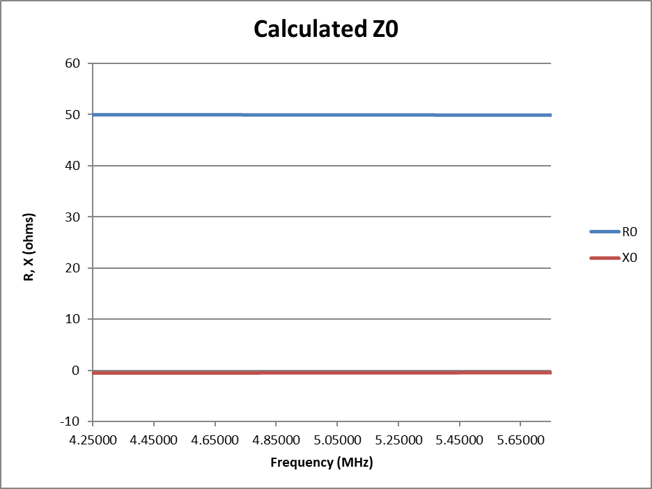
Lossless Line

A Lossless Line has imaginary part of Zo equal to zero and the real part of γ equal to zero.

Practical line

A practical line has non-zero imaginary part of Zo and non-zero real part of γ, and these are frequency dependent.

Under standing waves, attenuation along a practical line is not uniform, in most practical applications conductor loss/m is higher than dielectric loss so loss is higher near current maxima than near current minima.

For the purpose of this article, it is the frequency dependence of Zo, particularly the non-zero imaginary part that is significant.

A model

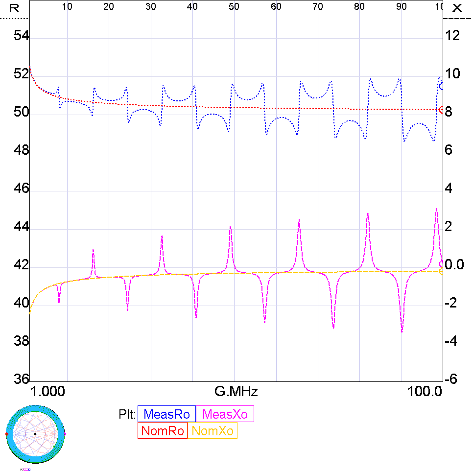
A model of a load similar to a 7MHz half wave dipole fed with 10m of RG58A/U was created in Simsmith to provide a basis for discussion. Whilst the model is subject to some errors computation, it is much less than comparing two field measurements at both ends of a transmission line.

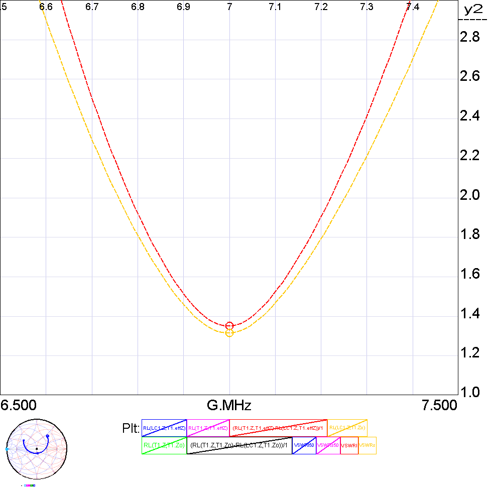
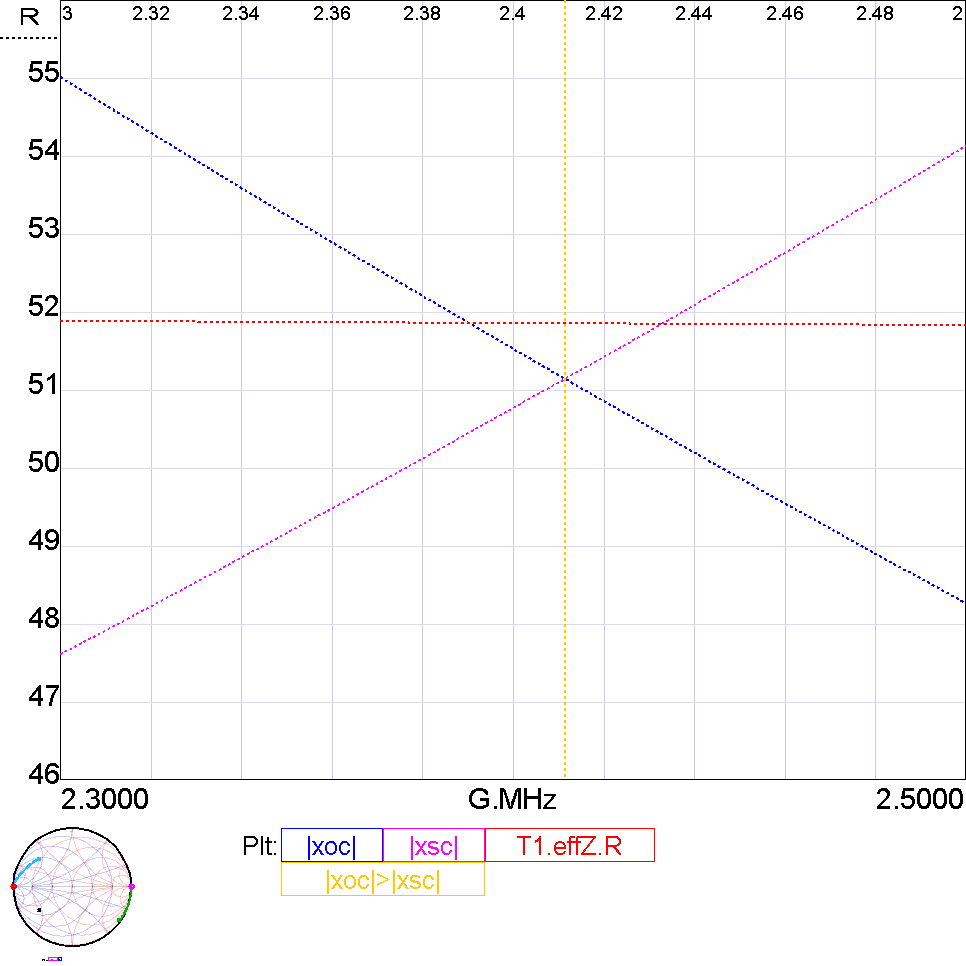
VSWR at each end of the transmission line

Let’s look at the ACTUAL VSWR. Actual means that if you were to observe the standing waves on the line (eg with a voltage probe), this is the VSWR you would expect to observe.

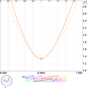
Firstly, observe that the source end VSWR (orange) is a little lower than the load end VSWR. This is by virtue of the attenuation on the line. The difference between the two can be calculated, but it is moderately complicated. Continue reading Where is the best place to measure feed point VSWR – error in Zo

Implementation of G5RV inverted V using high strength aluminium MIG wire – 7 year review

This article continues on from Implementation of G5RV inverted V using high strength aluminium MIG wire documenting review after 7 years operation under a wide range of temperature, humidity and wind conditions. It adds some contemporaneous pics of some parts of the system.

Support structure

Above is a view of the steel mast (2021) with the Inverted V G5RV rigged from the top of the 11m mast using a halyard through a purchase on a small gibbet to offset the antenna and feed line from the mast. There are lateral guys at 7m height, and the left hand one is non-conductive synthetic fibre rope. Atop the mast is a 2m/70cm vertical.

Above is a view of the feed point (2023) of the G5RV at 1mm AGL. The galvanised telescopic TV mast is 55 years old and starting to show signs of rust, likewise for the gibbet which was painted with cold gal back then. Continue reading Implementation of G5RV inverted V using high strength aluminium MIG wire – 7 year review

Thoughts on the ARRL EFHW antenna kit transformer

Several readers have asked my thoughts on the ARRL EFHW kit.

I have not built and measured the thing, but have done the first step in a feasibility study.

The transformer design is not novel, it is widely copied and this may be one of the copies. The design is usually published without any meaningful performance data or measurements.

The article Select a ferrite core material and sufficient primary turns for a low InsertionVSWR 50Ω broadband RF transformer – comparison of measured and predicted laid out a method for approximating the core loss of a EFHW where the load is adjusted to that input VSWR50=1, ie input Z=50+j0Ω.

That method will be applied here for a good initial estimate of core loss.

I will present calcs for 80m and 40m since there are lots of articles and videos encouraging people to extend the antenna to 80m (with and without a loading coil).

It is quite practical to build an EFHW transformer with less than 0.5dB (11%) core loss.

Amidon FT240-43 toroid with 2t primary

The first point to note is that Amidon’s 43 product of recent years is sourced from National Magnetics Group, and is their H material. It is not a good equivalent to Fair-rite’s 43 mix.

Let’s make a first estimate of core loss at 3.5MHz.

We can estimate the complex permeability which is needed for the next calculation. Continue reading Thoughts on the ARRL EFHW antenna kit transformer

Determination of transmission line characteristic impedance from impedance measurements – eighth wave method

For a lossless line, the reactance looking into short section and open circuit terminated line sections is \(X_{sc}=Z_0 \tan \beta l\) and \(X_{oc}=Z_0 \frac1{\tan \beta l}\).

Noting that when \(\beta l= \frac{\pi}{4}, \tan \beta l=1\) so when the line section is π/4ᶜ or 45° or λ/8, then \(|X_{sc}|=|X_{oc}|=Z_0\).

We can use this property to estimate Zo of an unknown practical low loss transmission line by finding the frequency where \(|X_{sc}|=|X_{oc}|\) and inferring that \(Z_0 \approx |X|\).


Above is a chart created using Simsmith’s transmission line modelling of the reactance looking into short section and open circuit terminated 10m sections of RF174. The blue and magenta lines intersect at X=51.16Ω whereas red R0=51.85Ω, about -1.3% error. The error depends on line loss, line length, frequency and the characteristics of the terminations. Continue reading Determination of transmission line characteristic impedance from impedance measurements – eighth wave method

Determination of transmission line characteristic impedance from impedance measurements #2

Determination of transmission line characteristic impedance from impedance measurements discussed issues with the short circuit and open circuit terminations used with measurement of Zoc and Zsc for calculation of characteristic impedance of a line section.

Included was a model of the effect of small delay offset in one of the termination parts on an example scenario.

This article gives a Simsmith model that readers might find interesting to explore the effects of line length, offset, line characteristics, and frequency.

I have issues with Simsmith modelling of transmission lines, but nevertheless the model is informing.

The above example is 6m of RG58A/U with 5mm offset in the short circuit termination. Continue reading Determination of transmission line characteristic impedance from impedance measurements #2

Relationship between radiation efficiency and minimum VSWR for common short helically loaded verticals

This article explores the relationship between radiation efficiency and minimum VSWR for common short helically loaded verticals.

For clarity, \({RadiationEfficiency}=\frac{FarFieldPower}{InputPower}\).

Such antennas are often advertised with a “minimum VSWR” or “VSWR at resonance” figure, but rarely show gain figures. One might wryly make the observation that that is how one might sell dummy loads rather than antennas.

Well, these things do radiate, so they are not very good dummy loads. Lets explore a theoretical example on the 40m band to inform  thinking.

Unloaded vertical

Above is a NEC5.2 model of a vertical on a wagon roof. Continue reading Relationship between radiation efficiency and minimum VSWR for common short helically loaded verticals

Determination of transmission line characteristic impedance from impedance measurements

Measured impedances looking into a uniform transmission line section with short circuit (SC) and open circuit (OC) terminations can provide the basis for calculation of characteristic impedance Zo.

We rely upon the following relationships:

\(Z_{sc}=Z_0 \tanh (\alpha + \jmath \beta )l\\\) and

\(Z_{oc}=Z_0 \coth (\alpha + \jmath \beta )l\\\)

Rearranging the formulas and multiplying, we can write:

\(Z_0^2=\frac{Z_{sc}}{\tanh (\alpha + \jmath \beta )l} \frac{Z_{oc}}{\coth (\alpha + \jmath \beta )l}\\\) \(Z_0^2=\frac{Z_{sc}}{\tanh (\alpha + \jmath \beta )l} Z_{oc}\tanh (\alpha + \jmath \beta )l\\\)

The tanh terms cancel out… provided the arguments are equal. Focus on length l, l for the short circuit measurement might not equal l for the open circuit measurement if the termination parts are not ideal (and they usually are not).

If the tanh terms cancel, we can simplify this to \(Z_0=\sqrt{Z_{sc}Z_{oc}}\). This is commonly parroted, apparently without understanding or considering the underlying assumption that l is equal for both measurements.

Another big assumption is that it is a uniform transmission line, ie that the propagation constant β is uniform along the line… including any adapters used to termination the line.

The third assumption is that the measured impedance values are without error.

Above is a plot of calculated Zo for a theoretical case of a line of ~10m length of Belden 8267 (RG213A/U) around the frequency of first resonances. This calculation essentially imitates perfect measurements of perfect DUTs. Continue reading Determination of transmission line characteristic impedance from impedance measurements

NanoVNA-App v1.1.209-OD15 released

Most of the changes I have made to NanoVNA-App have been to align it with accepted standards and conventions.

This change is to the format of saved Touchstone, .s1p and .s2p, files.

Though the relevant specification is silent on the permitted decimal separator, the only one shown in examples is “.” so it is reasonable to interpret that the required separator is “.” which makes the file format locale independent (as were the first instruments using Touchstone format.

This release of NanoVNA-App writes “.” decimal separator, independent of locale.

The original reading code which was tolerant of either “.” and “,” is maintained, so it will continue to open files which might have been (incorrectly) saved using “,”.

NanoVNA-App-Setup-v1.1.209-OD15