When I was a student at TAFE in 1970, a teacher, Milton Moore, explained why the lab power supplies that were used, Perini & Scott 30V 2A, were the largest power supplies given their modest capability.
He explained that they were almost student proof. He went on the classify students in three categories, the average students constituted the bulk, then there were the quite inept who damaged the best equipment by doing things that no one could have anticipated, and the very bright who sought to understand equipment and expose their weakness.
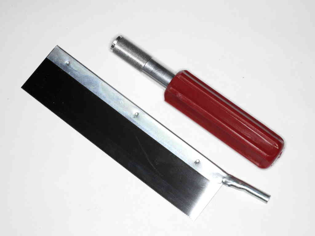
Milton explained that they tested these power supplies using the rat tail file and hacksaw blade test. One output terminal was attached to the rat tail file and the other to a hacksaw blade, the voltage and current were set to max and the rat tail file and hacksaw blade were rubbed together yielding a shower of sparks… and possibly smoke from the DUT.
At the time I was very interested in overcurrent protection of linear regulators, so this was especially interesting.
ua723 – the darling of power supply designers of the time
Lets look at the issue with the ua723, recently released at that time and appearing in lots of designs.
 Above is a schematic from the ua723 datasheet. Rsc is the current sense resistor and it is chosen to develop 0.6V at the current limit, so for instance in a 20A power supply it would have a value of 0.6/20=0.03Ω. So, the current sense circuit presents a Thevenin equivalent circuit of Vth=Rsc*I and Rth=Rsc. Continue reading Milton Moore’s power supply test