Chinese CH2 terminal block (CH1 CH3)

I purchased some CH2 terminal blocks on eBay. They were advertised as 250V AC, 10A, to suit 2.5mm^2 conductors.

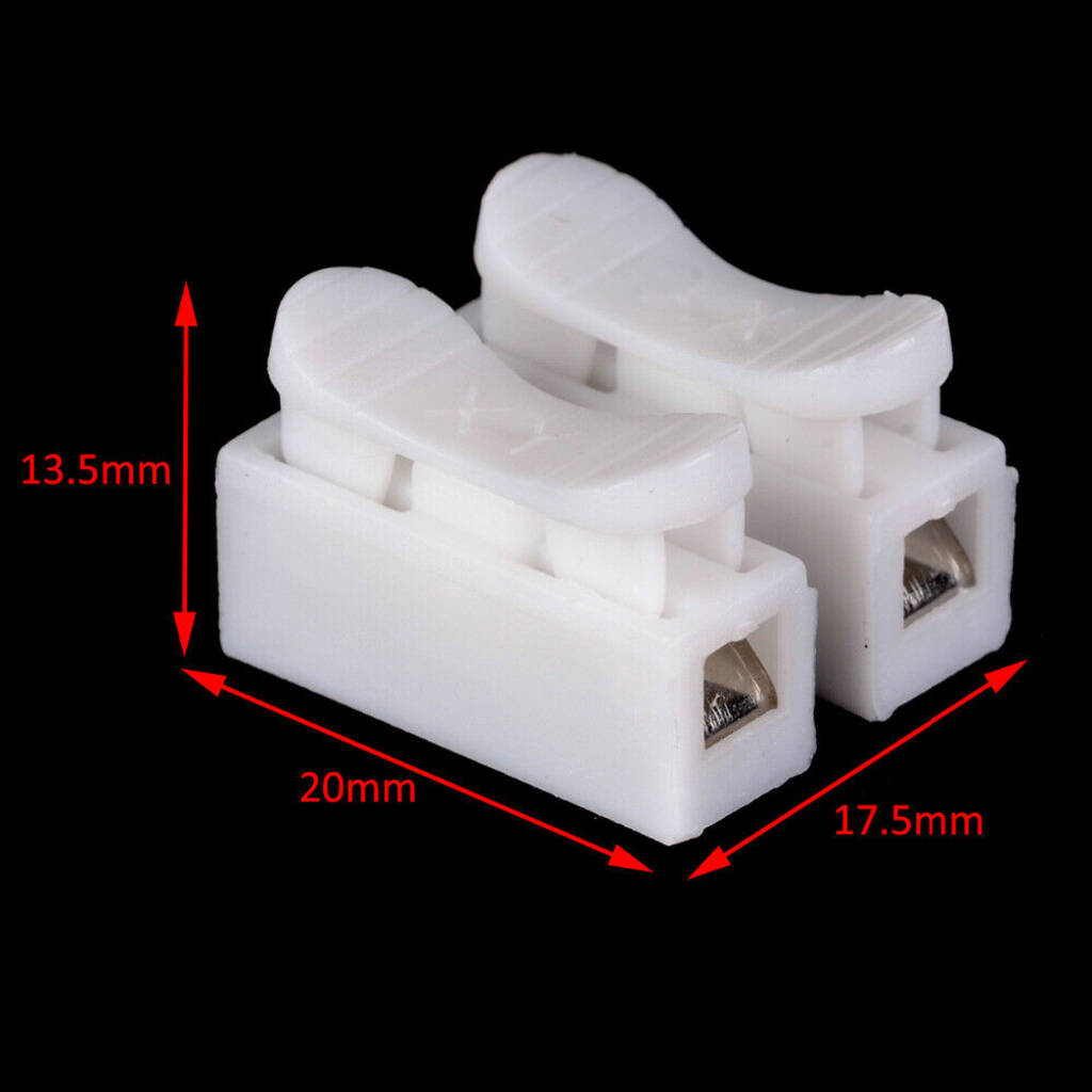
Above is the seller’s pic of the terminal block.

Features:
– Fast wiring
– Prevents the wire from shorting out
– Free drilling screws, increase the speed of assembly
– Can completely replace electrical tape
– Cost savings
– Fast、efficient and safe
– Widely used in the wire connection,especially for LED Lighting Ceiling
– lamp dedicated wiring clip.

Specification
– Material: PP Flame Retardant Plastic
– Reed material: Manganese Steel Sheet
– Color: White
– Voltage: 220V
– Current: 10A
– Type: 2Pin Connector
– Style:Self-locking Cable Connector
– Temperature: -40 to 150 Degrees Celsius
– Wiring: Wiring Capacity From 0.5-2.5 Square Wire
– Size: CH-2:Approx. 20*17.5*13.5mm

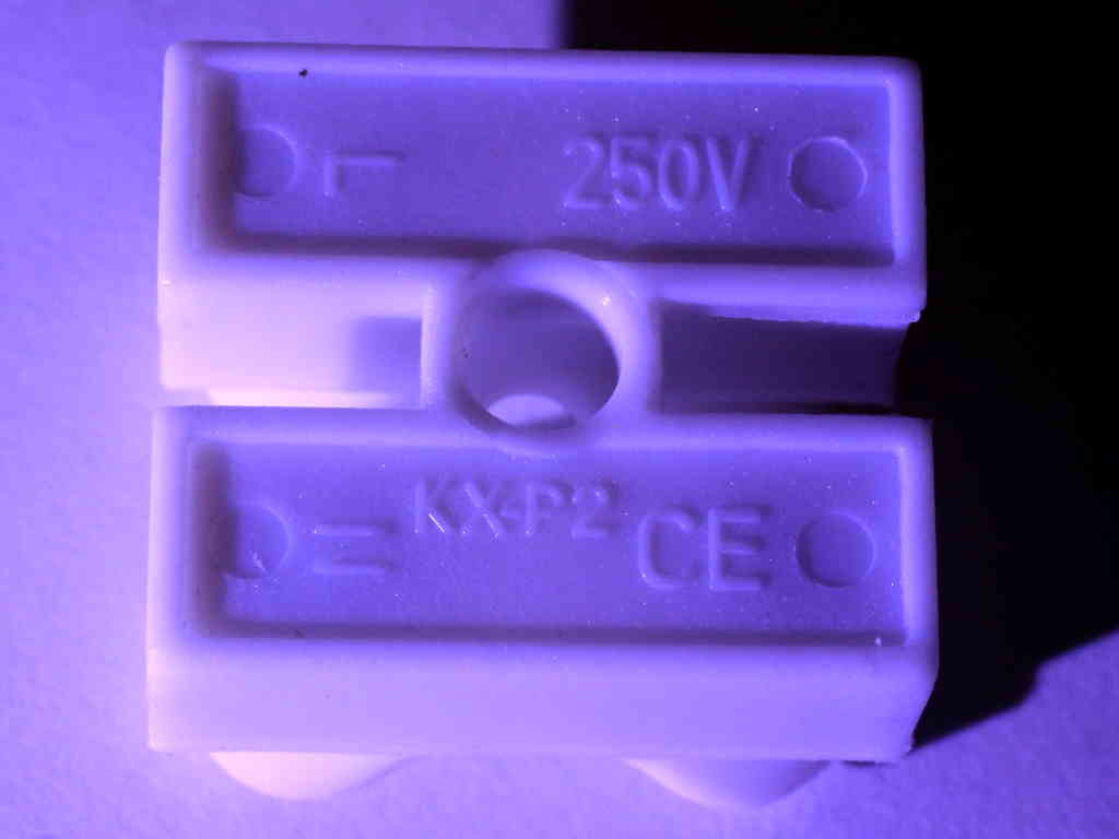
Close inspection cause me concern for their performance, there is no current rating marked. The product is labelled KX-P2 and appears to be a product of Foshan Shunde Kaixiang Electrical Co Ltd, but the Chinese being great copyists, this may have come from another source. Continue reading Chinese CH2 terminal block (CH1 CH3)

Conversion of oyster luminaire to LED

I purchased a kit to convert a oyster luminaire to single colour LED on eBay. The kit was nominally 18W, supplied with the 5730 LED plate and driver module for about $10 incl shipping.

A cautionary note: do not play with these things unless you have the necessary competencies.

The thing was packed in nothing more than a plastic mailing bag and was bent in several places in transit from China. It was not usable in that state and some LEDs were not working so my money was refunded in full (after the usual tug-o-war eventually resolved with eBay intervention). It had to be straightened to be usable, but at the risk of damaging LEDs and possibly cracking or compromising the insulation layer.

Above, after flattening the back plate, nearly half the LEDs are not working. Continue reading Conversion of oyster luminaire to LED

MFJ ATU hand effects on capacitor knobs

The problem

Users of some ATUs may have noticed particular sensitivity to hands on the capacitor adjustment knobs. It is a common problem with cheap implementations of the T match as the capacitor rotor is usually at high RF voltage and if that shaft is extended to the adjustment knob, under certain circumstances tuning becomes very sensitive to hands on the knobs.

In some of these implementations, if the users hand touches the metal grub screw in the knob, or the metal panel bushing behind the knob they may get a significant RF burn.

The cause

Let’s use the MFJ-949E as a discussion example. It is a T match, and the metal capacitor shafts in the knobs and panel bushings carry RF voltages.

So why is this only sometimes a problem?

The RF voltage across the coil, and impressed on the capacitor shafts can be extremely high when using loads with small resistance and large negative reactance, more so on the lower bands. Continue reading MFJ ATU hand effects on capacitor knobs

nanoVNA-H – de-embedding the feed line in remote measurement

There are often times when it would be useful to transform measurements made looking into a feed line to the other end of the feed line.

Ham lore

Common advice given by online ham experts include:

  1. it just cannot be done, the best (only) point to measure an antenna is at the feed point;
  2. it can be done, but only with an integral number of half waves of feed line;
  3. use the port extension facility in your software;
  4. use software package x;
  5. do an OSL cal with the feed line being part of the fixture.

Continue reading nanoVNA-H – de-embedding the feed line in remote measurement

WIA 4:1 current balun – further measurements

4-101a

I mentioned in my article WIA 4:1 current balun that the use of a single toroidal core in the above graphic compromises the balun. This article presents some simple measurements and analysis that question whether the balun works as so many users think.

The popularity of the balun derives from the work of VK2DQ and is often known as the VK2DQ 4:1 current balun (though probably not his invention).

Analysis at the limits

Often, analysis of a network as frequency approaches zero or infinity can simplify the analysis whilst allowing a reasonable test of the sanity of the design.

Above is a conventional transformer schematic of the WIA 4:1 current balun on a perfectly symmetric (balanced) load. At frequencies where the electrical length of each winding is very short, we can assume negligible phase delay along or between windings, simplifying analysis greatly. Continue reading WIA 4:1 current balun – further measurements

4:1 current balun – identifying bad ones

Correspondents have informed me that the balun dealt with in article 4:1 current balun – review and fix and variants are very common. This article gives a checklist of common issues and some basic measurements using an antenna analyser that should reveal some issues without breaking into a sealed assembly.

Introduction

Baluns are commonly employed to obtain nearly balanced feed line currents (ie negligible common mode current) in two wire lines or negligible common mode current on coaxial feed lines. This article discusses baluns for that application.

A very common 4:1 current balun is Guanella’s 4:1 current balun, but there are others including pretenders.

Three common 4:1 current baluns

Guanella 4:1 current balun

(Guanella 1944) described a 4:1 current balun in his 1944 article, he did not show the winding pairs coupled by a magnetic core as shown above.

Guanella421

Above is Guanella’s circuit, and he does not show coupling between the two winding pairs.

Properly implemented, this device is known to work very well.

Sevick’s single core 4:1 current balun

Let us look at Sevick’s device because it underlies so many failures.

If you look at it very carefully, you will see that the two output wires emerge from opposite sides of the core, the left hand wire exiting under the core was wound from front to back of the core and the right hand wire exiting on top of the core was wound from back to front of the core. Continue reading 4:1 current balun – identifying bad ones

4:1 current balun – review and fix

This article reports tests on two 4:1 current balun configurations – a collaboration between Bruce, VK4MQ, and myself.

Purported current balun on a single magnetic core

Above is an attempt at a 4:1 current balun on a single core. Note that this is NOT wired in the insane series opposed connection of the WIA 4:1 current balun. Note also that this is NOT a Guanella 4:1 current balun (see below).

Lets measure the Insertion VSWR by placing a good 200+j0Ω load on the output terminals and measuring input VSWR over the range 1-30MHz. This load is what we will call an Isolated Load meaning it has only two terminals, and the current that flows into one terminal must flow out of the other terminal… in other words, the current MUST be balanced (ie equal magnitude but opposite phase currents in the two terminals)… we will come back to the Isolated Load later.

Above, measured InsertionVSWR. It is not too good, but not very bad either. Broadly the balun gives an almost reasonable 4:1 impedance transformation from load to input. Continue reading 4:1 current balun – review and fix

nanoVNA-H – Port 2 attenuator for improved Return Loss

nanoVNA-H – measure 40m low pass filter for WSPRlite flex describes measurement of the response of a filter.

The filter is of a type that depends on its source and termination impedance for as designed performance.

The article mentioned the use of a 10dB attenuator on the nanovna-h Port 2 for the purpose of improving the accuracy of the load impedance for the filter.

Like most low end vnas, the nanoVNA Port 2 VSWR or Return Loss is not wonderful, not as good as needed for some types of measurement. Return Loss can be improved by placing an attenuator ahead of the port. The nanoVNA-H v3.3 already includes an attenuator on the PCB, and the nanovha-H v3.4 increased that attenuation by about 5dB to improve Return Loss by about 10dB.

In my own case, I am using a nanoVNA-H and upon measurement of |s11| (-ReturnLoss) I determined that it needed to be improved by 20dB for my use so I purchased and installed a 10dB attenuator semi permanently on the Port 2 connector.

Above, the 10dB attenuator is semi permanently attached to Port 2 and also serves the purpose of a connector saver. There is a connector saver semi permanently attached to Port 1. Continue reading nanoVNA-H – Port 2 attenuator for improved Return Loss

A common mode choke for a VDSL pair – LF1260 core

This article describes a common mode choke intended to reduce RF interference with a VDSL service.

The MDF is located where the underground cable enters the building. From here it rises vertically and travels some 25m across the ceiling to the VDSL modem. Continue reading A common mode choke for a VDSL pair – LF1260 core

nanoVNA-H – measuring an inductor – is it a no-brainer?

Let’s explore measurement of a test inductor with the nanovna.

Above is the test inductor, enamelled wire on an acrylic tube.

An online expert’s advice make this task look like a no-brainer:

For a 100 nH inductor you are probably using an air wound coil so you won’t see that much change in inductance with frequency. However, inductors made with toroids will because the permeability of the core goes down with frequency.

So, this is an air cored inductor, permeability is approximately that of free space, a constant 4πe-7 independent of frequency. Nevertheless we will see that apparent inductance can change with frequency. Continue reading nanoVNA-H – measuring an inductor – is it a no-brainer?