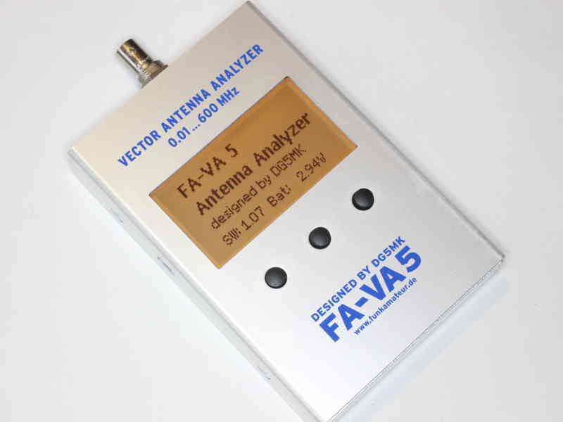
I recently acquired a FA-VA5 antenna analyser.
Before trusting measurements made with any instrument, its behaviour should be validated, and this article documents issues discovered in one thread of tests. The developer does not like the term “defects”, he prefers “issues”, a soft denial of “problems”.
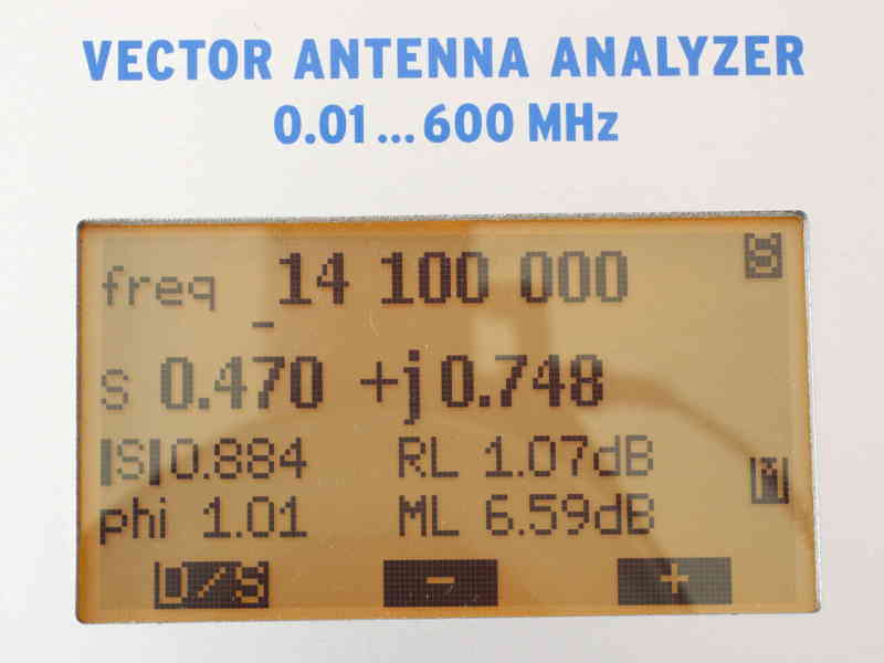
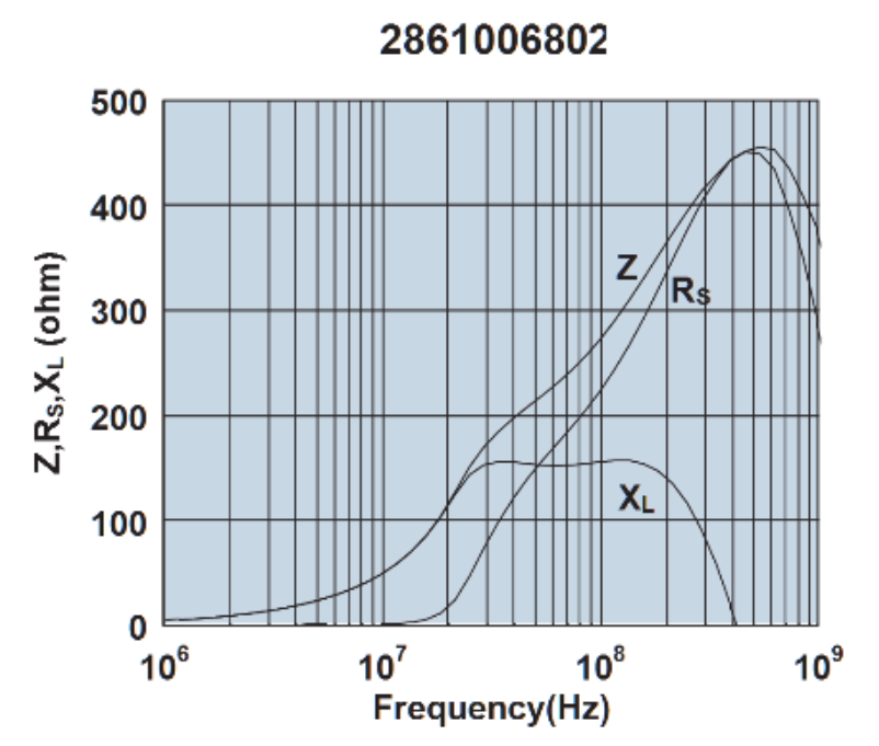
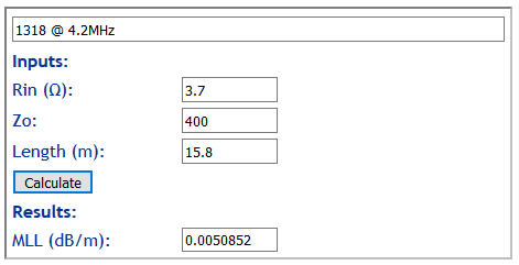
So, the test scenario is the VA5 measuring the impedance looking into a 35m length of RG6 coax with an open circuit at the far end. The VA5 has been SOL calibrated with the higher quality loads sold by SDR-kits, and the test is a 3.5MHz. The firmware is the latest, v1.08 (about 3 months old).
The screenshots are taken with a camera, there does not seem to be a method of uploading screenshots to a PC.
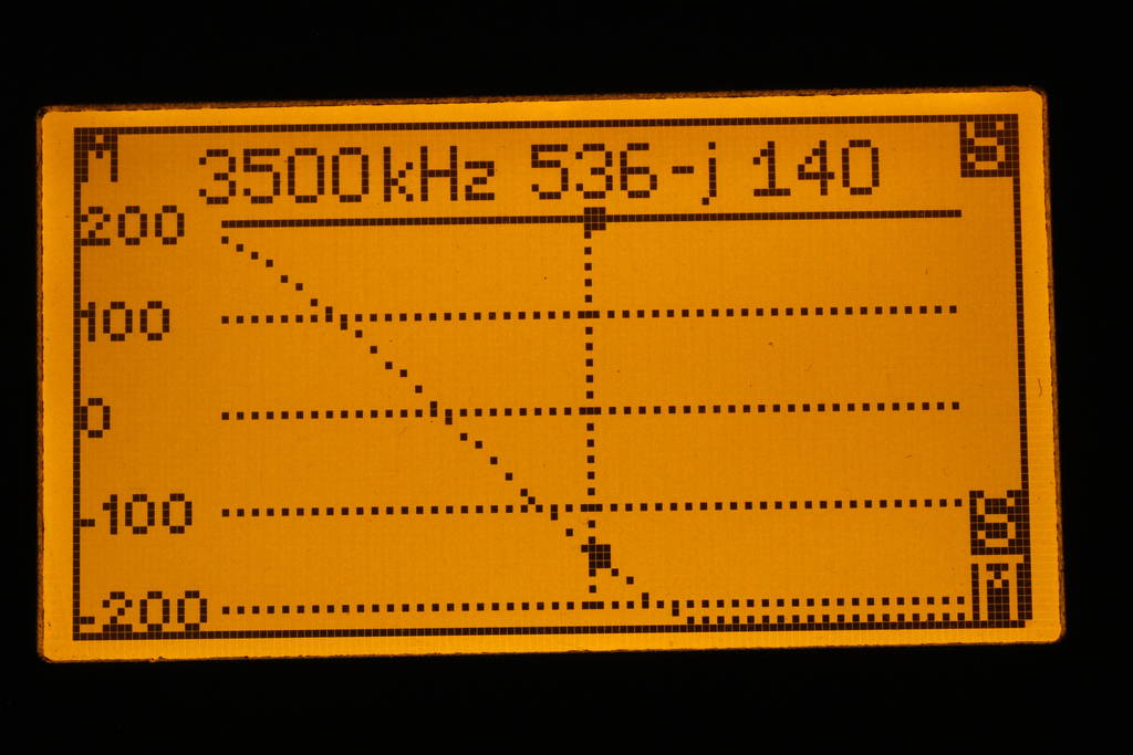
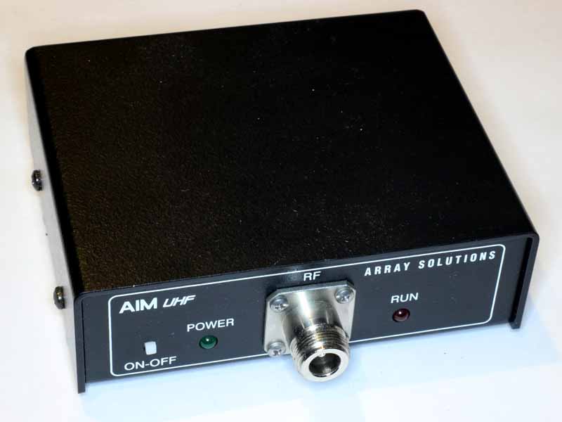
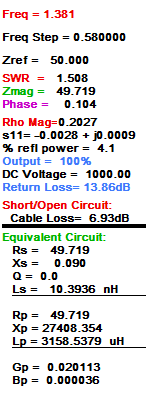
Above is a swept Z measurement just above the half wave resonance of the line section. The impedance at the marker is comparable with that measured using an AA-600, so I would accept that it is probably correct. The graph is another matter. Continue reading A fourth round with the FA-VA5 antenna analyser