Conductors for a Guanella 1:1 balun – discussion

This article discusses some design factors that should be considered when designing / implementing a Guanella 1:1 balun (often known as a common mode choke).

The behavior of a Guanella 1:1 balun can conveniently be separated into its concurrent common and differential modes.

It is the differential mode that is of most interest when it comes to conductors. Continue reading Conductors for a Guanella 1:1 balun – discussion

High voltage test of a couple of PTFE insulated silver plated copper wires

This article documents a high voltage test of a couple of PTFE insulated silver plated copper wires.

In each case, a single wire is tested, one electrode to the wire and another being an alligator clip clipped onto the wire about 30mm from the end. This approximates a knife edge test which subjects the insulation to the highest electric field strength.

At the time of the test, temperature was 21° and relative humidity 65%. Whilst not extreme humidity, it is sufficient to degrade breakdown often giving rise of an arc over the surface of the wire to the cut end. For that reason, about 30mm of insulation is left clear at each end. Continue reading High voltage test of a couple of PTFE insulated silver plated copper wires

An example and explanation of unexpected common mode choke flashover

An online discussion is developing the design of an ultimate common mode choke, at it reached a stage considered final when a transmit test revealed it could not withstand the unstated transmitter power.

The designer did report measurement at the choke looking into the feed line giving Z=493-j740Ω @ 3.8MHz. There are questions about the validity / uncertainty of the measurement, but let’s take is as correct for the purpose of this discussion.

We can calculate the expected differential peak voltage at a given power level at the point where Z=493-j740Ω. Continue reading An example and explanation of unexpected common mode choke flashover

Using complex permeability to design with Fair-rite suppression products

Fair-rite allocates some of its closed loop ferrite products to two different categories:

  • inductive; and
  • suppression.

Sometimes the same dimensioned cores are available in both categories with different part numbers and possibly different prices, implying some real difference in behavior, eg 5943003801 and 2643803802 are both FT240-43 sized cores.

Material datasheets often contain a note like this from the #43 datasheet:

Characteristic curves are measured on standard Toroids (18/10/6 mm) at 25°C and 10 kHz unless otherwise indicated. Impedance characteristics are measured on standard shield beads (3.5/1.3/6.0 mm) unless otherwise indicated.

I sought to clarify my interpretation of this clause by asking Fair-rite …whether the published material permeability curves / tables apply to suppression product. Can I use the published permeability curves / tables to predict inductor impedance reliably for suppression products?  Fair-rite’s Michael Arasim advised… Continue reading Using complex permeability to design with Fair-rite suppression products

Calculate ferrite cored inductor – rectangular cross section – enhancement – chamfered corners

The calculator Calculate ferrite cored inductor – rectangular cross section has until now assumed that the toroid has sharp corners. The corner treatment varies across commercial products, some are burnished which removes very little material, some have a chamfer or bevel, some are radiused. All of these treatments give rise to a very small error in calculated ΣA/l.

The calculator has been revised to include 45° chamfers of a specified length on all four corners. If the chamfer angle differs, the error is very small in the range 30-60°. If the corners are radiused, use the radius as the chamfer length, the error is very small. Continue reading Calculate ferrite cored inductor – rectangular cross section – enhancement – chamfered corners

Jaycar LO1238 ferrite core

Over many years, the Jaycar LO1238 has appeared in some of my projects. I recommended them for a range of applications, particularly applications optimised for low HF.

Above, the core is 35x21x13mm, a mid sized core, two used in my redesign of a commercial balun and implemented by VK4MQ . The mid size limits dissipation, but compactness can be an advantage. The cores sell for less than $4.00 per core and are readily available in Australia. Continue reading Jaycar LO1238 ferrite core

what-exactly-happens-to-the-signals-hitting-a-common-mode-choke?

An image from what-exactly-happens-to-the-signals-hitting-a-common-mode-choke doesn’t quite look right.

In respect of the first part, inductance \(L=\frac{\phi(i)}{i}\) so if the windings are equal, half the total current flows in each winding and each contributes flux due to i/2, total current is i, total flux is twice that due to i/2, so the inductance of the parallel equal windings is the same as if i flowed in a single winding, ie L of the combination is the same as the inductance of each of the equal windings alone. Continue reading what-exactly-happens-to-the-signals-hitting-a-common-mode-choke?

Some pretty woolly thinking about the operation of common mode chokes in antenna systems

One of the notions one often sees discussed is that at RF, some device inserted in a relatively long (meaning wrt wavelength) conducting path is likely to lead to interruption of the circuit in the way that a switch might in a DC circuit. Another variant is one where current flows on one side of the device and not the other… a fence as explained in the following text by one poster.

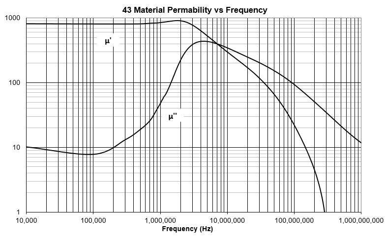
With a current balun or CM choke, it is the reactance (inductance) that is mostly responsible for the balun action. In the case of the choke balun, beads installed along the coax at the feed with 31 or 43 material, they form a reflective ‘filter’. There is some absorption, but most of the action is due to reflection from the inductive reactance they form installed on a conductor. As such, they form a high-Z isolation point between the feeder and the antenna center, assuming they are installed at the feedpoint of the doublet. In the case of the CM choke, the common mode currents are reflected by the inductive reactance of the windings as with the current balun and the balance of current between the two conductors is forced through induced opposing magnetic currents within the cone. This is the reason I prefer the CM choke for the purpose. In either case, the common mode current is reflected to a large extent by the inductive reactance back where it originated. Installation of a balun at the feedpoint of a doublet does not make the CM currents go away, it just establishes a ‘fence’ for those currents between non-antenna associated currents (on the outside of the feedline) and the radiating structure.

Let us explore some NEC models with three ‘devices’ to attempt to confine current to the lower conductor:

  • a gap;
  • a large pure inductive reactance;
  • a large pure resistance.

Gap

The first is at 10MHz a vertical conductor over a perfectly conducting earth, and space 0.1m above it, another vertical conductor.

Above is the current distribution showing phase and amplitude, the gap is at one third the height. It is not totally clear from the 2D rendering of a 3D characteristic, but the phase in the upper two thirds is opposite to the phase in the lower third, and this is by virtue of the lengths which are approximately a quarter and half wavelength. Continue reading Some pretty woolly thinking about the operation of common mode chokes in antenna systems

Measurement of recent ‘FT240-43’ core parameters

This article reports measurement of two ‘FT240-43’ cores (actually Fair-rite 5943003801 ‘inductive’ toroids, ie not suppression product) purchased together around 2019, so quite likely from the same manufacturing batch. IIRC, the country of origin was given as China, it is so for product ordered today from element14. The measurements are of 1t on the core, with very short connections to a nanoVNA OSL calibrated from 1-50MHz.

Above, the measurement fixture is simply a short piece of 0.5mm solid copper wire (from data cable) zip tied to the external thread of the SMA jack, and the other end wrapped around the core and just long enough to insert into the inner female pin of the SMA jack. Continue reading Measurement of recent ‘FT240-43’ core parameters

nanoVNA – measuring cable velocity factor – demonstration – open wire line

The article nanoVNA – measuring cable velocity factor – demonstration demonstrated measurement of velocity factor of a section of coaxial transmission line. This article demonstrates the technique on a section of two wire copper line.

A significant difference in the two wire line is that we want the line to operate in balanced mode during the test, that there is insignificant common mode current. To that end, a balun will be used on the nanoVNA.

Above, the balun is a home made 1:4 balun that was at hand (the ratio is not too important as the fixture is calibrated at the balun secondary terminals). This balun is wound like a voltage balun, but the secondary is isolated from the input in that it does not have a ‘grounded’ centre tap. There is of course some distributed coupling, but the common mode impedance is very high at the frequencies being used for the test. Continue reading nanoVNA – measuring cable velocity factor – demonstration – open wire line