Desk study of M0DGQ’s 150W HF PA

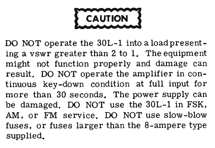
M0DGQ described a broadband HF PA in the Wythal Radio Club’s newsletter 2017-01, and rated it at 150W output. Note that this module does not include the necessary output filter which will probably lose 5-10% of the power from this module.

The PA uses a MRF9180 dual MOSFET operating on 26V supply.

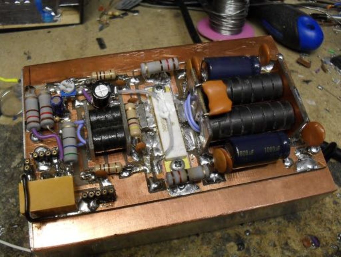
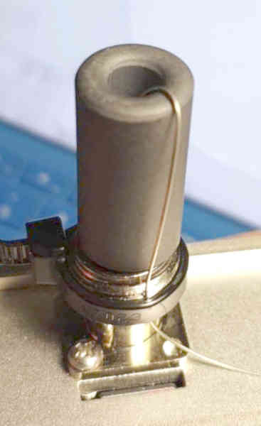
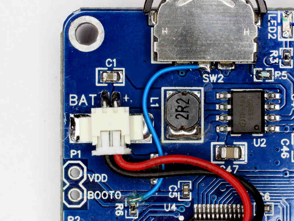
Above is the prototype PA. The text states very clearly that the output transformer uses a secondary of two turns of PTFE insulated wire, and the pic above does not provide evidence to the contrary.

Hmmm, experience suggests that may be too few turns. Continue reading Desk study of M0DGQ’s 150W HF PA

A desk review of the MiniPa100 kit – #1: characterise the output transformer

This article is one in a series of a desk review, a pre-purchase study if you like, of the MiniPa100 kit widely sold on eBay and elsewhere online.

One of the first questions to mind is whether it is likely to deliver the rated power, so let’s review the MOSFET output circuit design from that perspective.

Sellers mostly seem to need to obscure the MOSFET type in their pics, so essentially you buy this with no assurance as to what is supplied, no comeback if the supplied MOSFET is not up to the task. Online experts suggest the MOSFET is probably a MRF9120 (or 2x IRF640 in a 70W build). The amplifier claims 100W from 12-16V DC supply.

Note that this module does not include the necessary output filter which will lose 5-10% of the power from this module.

In this case Carlos, VK1EA, connected a sample output transformer (T2) core from a recently purchased MiniPa100 kit to a EU1KY antenna analyser. The fixture is critically important, it is at my specification. Continue reading A desk review of the MiniPa100 kit – #1: characterise the output transformer

Some pretty woolly thinking on measuring Thevenin equivalent source impedance of a ham transmitter

A ham seeking to optimise his station based on some measurements with a VNA and some modelling of a matching network posted the results of a test in the process.

The radio is an Icom IC-7300. I bypassed the built in tuner, transmitted a tone into my external tuner, adjusted it for SWR=1. I then disconnected the tuner from the radio, and measured the impedance looking into the tuner with a VNA. Surprisingly, (to me anyway) the result was a pretty good 53-j3 Ohms at 14 MHz.

What should we / have expected? It is an interesting case to study. Continue reading Some pretty woolly thinking on measuring Thevenin equivalent source impedance of a ham transmitter

Collins 30-L1 on FT-8

After a lot of grief with Excel trying to open and fix some 10 year old spreadsheets… finally…

I was recently asked about FT-8 on the Colling 30-L1 linear amplifier considering my article Collins 30L-1 and AM.

The first thing to note is the Colling 30-L1 manual cautions against AM and FSK:

That said, what are the reasons for such a prohibition? Continue reading Collins 30-L1 on FT-8

Baofeng BF-T1 (BF-9100) – initial impressions

I purchased two inexpensive Baofeng BF-T1 UHF portables (hand-helds) for use around the yard.

Key features:

  • LiIon pouch single cell battery that may be obtainable longer than proprietary batteries;
  • micro USB charger interface, internal charge / battery management;
  • programmable with CHIRP (channel table only);
  • chanellised operation, lockable keypad;
  • CTCSS support;
  • integrated antenna;
  • small and lightweight (110g with belt clip);
  • inexpensive.

The radio has been in the market for more than three years, so one might hope that design issues have been fixed in ‘mature’ product. Continue reading Baofeng BF-T1 (BF-9100) – initial impressions

AIM4170 – de-embedding the feed line in remote measurement – a simple match

At AIM4170 – de-embedding the feed line in remote measurement a set of measurements of a monoband antenna looking from the transmitter were analysed to de-embed the feed line and arrive at the indicated feed point impedance.

This article explores a simple series match to improve the load seen by the transmitter.

In the Simsmith model above, the estimated feed point impedance is imported into element L, then a series section of lossless 50Ω line to represent the coax in the common mode choke (balun), then a series section of lossless 75Ω to perform the impedance transformation, then a section of 50Ω lossless line to make up the required length to the transmitter. Continue reading AIM4170 – de-embedding the feed line in remote measurement – a simple match

AIM4170 – de-embedding the feed line in remote measurement

At nanoVNA-H – de-embedding the feed line in remote measurement I recently wrote on a procedure that can be very useful to refer measurements made at the transmitter end of a feed line to the antenna feed point.

A correspondent recently shared an AIM 4170 scan file of his 40m half wave dipole antenna system taken from the transmitter end of the coax and maintaining the common mode current path by bonding the shield of the coax connector to normal connection point on the transmitter.

Above is his graphic of the measurement looking into around 23m of RG58 feed line.

It shows the VSWR curve is quite classic in shape, the frequency of minimum VSWR is a little low, and the minimum VSWR is 1.478 which is quite within expectations of such an antenna. Continue reading AIM4170 – de-embedding the feed line in remote measurement

nanoVNA-H – another hardware fail – battery socket

I have a nanoVNA-H which has had many hardware problems, some designed in,but mostly sub-standard / faulty components.

Above, the latest repair. A new battery socket to replace the original that crumbled apart… sub-standard plastic from all appearances. This was from a reputable supplier, so it is probably a genuine Molex Picoblade part rather than some cheap Chinese knock off.

The blue wire is part of a mod to invoke the bootloader on power up, R5 was also changed to something small, 1k IIRC.

PS: a word of warning… always check polarity when fitting a battery, there is not rigid standardisation of connectors on LIPO batteries.

nanoVNA-H – Port 1 attenuator for improved what???

At nanoVNA-H – Port 2 attenuator for improved Return Loss I explained the reasons for essentially permanent attachment of a 10dB attenuator to Port 2 (Ch 1 in nanoVNA speak).


Above, the 10dB attenuator is semi permanently attached to Port 2 principally to improve the Return Loss (or impedance match) of Port 2, a parameter that becomes quite important when testing some types of networks than depend on proper termination (eg many filters). I should remind readers that the improvement in Port 2 Return Loss comes at a cost, the dynamic range of Port 2 is reduced by 10dB. Continue reading nanoVNA-H – Port 1 attenuator for improved what???