Osram Substitube tear down

I recently purchased two packs of 2x Osram Substitube LED replacements for a T8 36W florescent tube. The price per tube was about double that of a T8 fluorescent, and claimed life was 30,000 hours.

Note that LED life is usually an estimate of the time for 50% failure. Curiously, Osram individual LEDs have lower lifetime estimates for single LEDs, strings of LEDs will have lower lifetime, and lifetime for say 5% failures would be even lower. On the basis of experience with LED lighting, it might be optimistic to think that most of these lamps will last at least 5,000h.

In the event, three of four tubes had broken glass (yes, they use a glass tube much like the T8 fluorescent tube… though not sealed at the ends), and the other was DOA, no light output.

The LED driver is attached to pins at one end of the lamp, and covered by a label over the glass. Note that there are several incompatible schemes used in T8 fluorescent replacement LEDs, the other scheme bonds the adjacent pins at each end of the lamp and connects line and neutral to opposite ends. Osram calls this a “Type A” connection, and as the name suggests if can be fitted to an ordinary magnetic ballast luminaire PROVIDED the original starter is replaced with Osram’s “LED starter” which is actually a HRC fuse of around 1A rating.

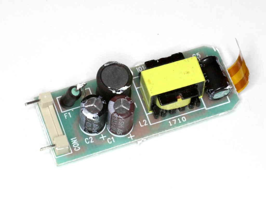
Above is the top view of the electronics. Continue reading Osram Substitube tear down

Towards understanding the YouLoop-2T at MF/lowHF

Small untuned loop for receiving – simple model with transformer gave a simple model for analysing a loop. If you haven’t already read it, you should. It provides a step towards understanding the YouLoop-2T at frequencies where is is a small loop (perimeter<λ/10).

Above is the Airspy Youloup-2T. Try to put the two turns thing out of your mind, it is misleading, panders to some common misunderstanding, and so does not help understanding.

This is somewhat similar to the simple loop, but now the transformer primary is connected to the loop gap terminals by two parallel sections of 50Ω transmission line, the combination being effectively a 100Ω with similar parameters to the component coax sections. Because of the series connection at the transformer and parallel connection at the loop gap, there is a 1:4 impedance transformation additional to that of the coax sections themselves. Continue reading Towards understanding the YouLoop-2T at MF/lowHF

A transmission line 1:4 impedance transformer

This article explains the operation of a simple nominally 1:4 impedance transformer using transmission line (TL) elements.

Above is a diagram of the device. The currents shown are differential currents in the coax (ie wholly inside the coax), the current on the outside of the shield is not shown on the diagram.

At very low frequencies it may be intuitive that \(V_1\approx V_2\) and \(I_1\approx I_2\), but as frequency increases, a more exact solution is needed. Continue reading A transmission line 1:4 impedance transformer

Small untuned loop for receiving – simple model with transformer

I have written several articles on untuned loops for receiving, as have others. A diversity of opinions abounds over several aspects, probably none more than the idea of an optimal load impedance for the loop.

This article analyses a simple untuned / unmatched loop in the context of a linear receive system (ie no IMD) of known Noise Figure. Continue reading Small untuned loop for receiving – simple model with transformer

nanoVNA-H – Port 1 attenuator for improved what???

At nanoVNA-H – Port 2 attenuator for improved Return Loss I explained the reasons for essentially permanent attachment of a 10dB attenuator to Port 2 (Ch 1 in nanoVNA speak).


Above, the 10dB attenuator is semi permanently attached to Port 2 principally to improve the Return Loss (or impedance match) of Port 2, a parameter that becomes quite important when testing some types of networks than depend on proper termination (eg many filters). I should remind readers that the improvement in Port 2 Return Loss comes at a cost, the dynamic range of Port 2 is reduced by 10dB. Continue reading nanoVNA-H – Port 1 attenuator for improved what???

nanoVNA-H – woolly thinking on MLL measurement

There is little doubt that the nanoVNA has made VNAs very popular in the ham community, possibly more so that any other device.

Eager owners are trying to apply them to solve lots of problems, often without sufficient knowledge or experience to properly inform the measurements.

An example that has a appeared a few times on online forums in the last weeks is measuring the matched line loss (MLL) of a section of RG6 coax… to inform a decision to discard it or keep it.

The common approach is to use a measurement of |s11| and to calculate Return Loss and infer the MLL.

DUT

For discussion, lets consider an example of 30′ of Belden 1694A RG6 solved in Simsmith. We should note that unlike most RG6 in the market today, this uses a solid copper centre conductor.

Short circuit termination

Some authors insist that the half return loss method is to be performed using a short circuit test section. Bird does this in their Bird 43 manual.

Above is a plot of calculated |s11| (-ReturnLoss) from 1 to 20MHz for the test section. The three plots are of |s11| wrt 50Ω, 75Ω and frequency dependent actual Zo (as calculated for the model). The cursor shows that the actual |s11| is -0.37474dB (ReturnLoss=0.37474dB). Using the half return loss method MLL=ReturnLoss/2=0.37474=0.187dB/m. Continue reading nanoVNA-H – woolly thinking on MLL measurement

RG6 cladding thickness report

N0TZU recently report his perception that a length of Logico COX3520 RG6 Quad cable he purchased exhibited higher than expected Matched Line Loss (MLL) at 10MHz.

Most RG6 type cable sold these days at low cost uses a copper clad steel centre conductor, and much of it has insufficient copper cladding thickness for copper like performance at HF.

Above is a pic N0TZU gave of the centre conductor cross section. It is possible to measure the cladding thickness from the pic knowing that the overall diameter is 1.024mm. The copper thickness measured 13.7µm, lets round it to 14µm. Continue reading RG6 cladding thickness report

nanoVNA-H – thinking laterally

A question was asked in an online forum specific to nanoVNA as to how the use the nanoVNA to check the attenuation loss in some old & weathered RG-6 (75 ohm) cables for the TV signal frequencies. Excuse the term attenuation loss, lets assume the poster is asking for matched line loss (MLL).

The assembled experts are offering solutions to transform the ports to 75Ω and make a measurement, deducting the loss of the transformation (minimum loss pads were suggested).

There is a very simple solution that should be quite practical for the scenario described. Let’s work through two examples using 35.5m of unbranded quad shield RG6 with CCS centre conductor (of unknown quality) for the DUT. Continue reading nanoVNA-H – thinking laterally