This article documents a station for propagation observations on 144MHz, in this case the antenna system part of the entire system.
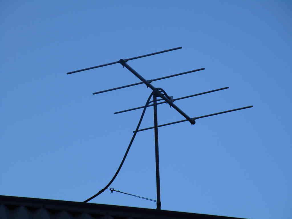
Above, the antenna is a 4 element Yagi with Gamma match. Continue reading 144MHz propagation experiment – antenna
This article documents a station for propagation observations on 144MHz, in this case the antenna system part of the entire system.
Above, the antenna is a 4 element Yagi with Gamma match. Continue reading 144MHz propagation experiment – antenna
In the quest for drivers for some 18W LED plates, I have placed 6 orders for non dimming nominally 300mA drivers for 18-24W LED plates.
The LED drivers originally supplied with the LED plates were rated at 180mA (10.8W) and measured 150mA (9.0W)
The tests here use an 18W LED plate, wired as 18 pairs of 0.5W LEDs in series for a total voltage of around 60V and 300mA for 18W.
Most orders have not arrived after several months, it appears some Chinese sellers are not shipping even though they have said they did. One shipment contained a single bare board with no details, it wasn’t ordered and without ratings was consigned to the trash.
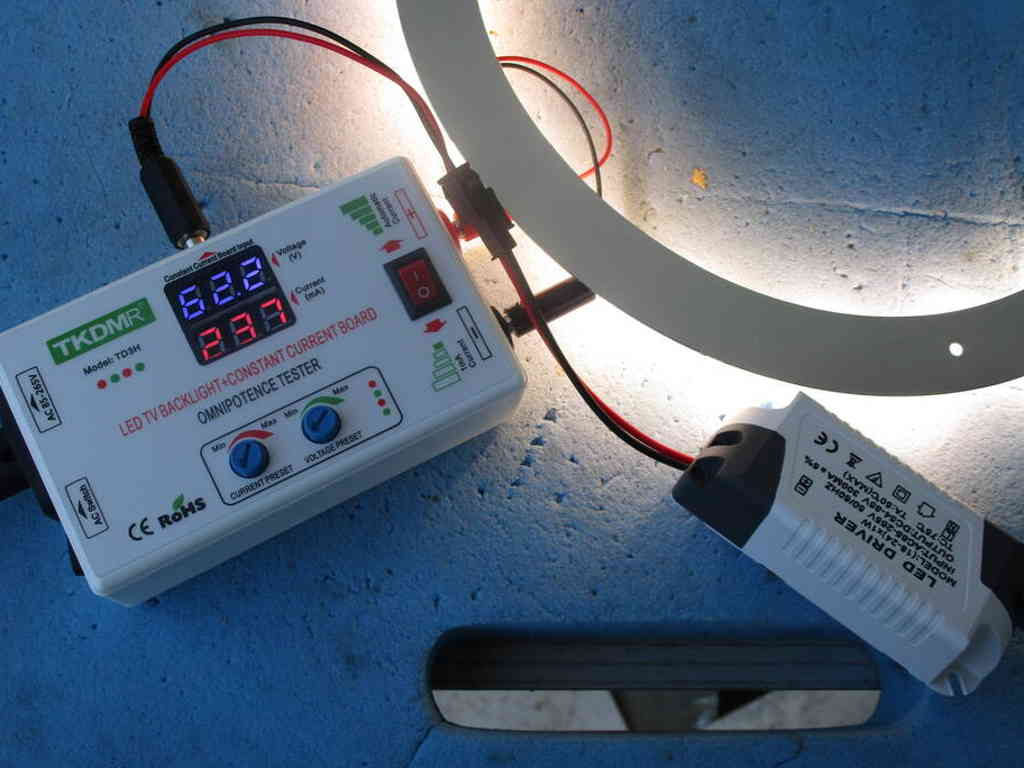
Above is a test of one type of LED driver rated at 300mA ±5%. It supplies 237mA which is 21% less than 300mA, hopelessly low on specification. The other four purchased were within 1% of the same current. Continue reading LED Driver measurement – #2
The D44-22P-01 is a Chinese LED plate rated at 15W and operates directly from 230VAC with an integrated driver.
It was purchased to explore the configuration of LEDs with integrated driver, and this driver looks deceptively simple.
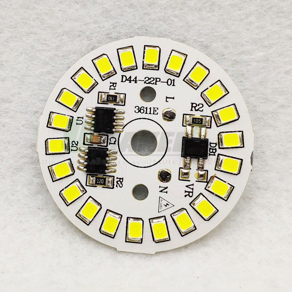
The chips are JZ1009AE, a LED current driver. The 22 2835 LEDs are 9V LEDs for a string voltage of 200V. Continue reading LED plate analysis – D44-22P-01
A new version of Antscope2 has been released.
Online posters are excited that it supports some versions of nanoVNA, and one thread attempts to answer the questions:
The SWR image shows that the SWR minimum is at the center phase angle as you would expect. My question is:
what are the other points that look like resonance,
and should I trim my antenna based on phase?
If so which one?
They are interesting questions which hint the ham obsession with resonance as an optimisation tartget.
Properly interpreting VNA or analyser measurements starts with truly understanding the statistic being interpreted.
In this case, the statistics being discussed are Phase and VSWR, and their relationship.
What is the Phase being discussed?
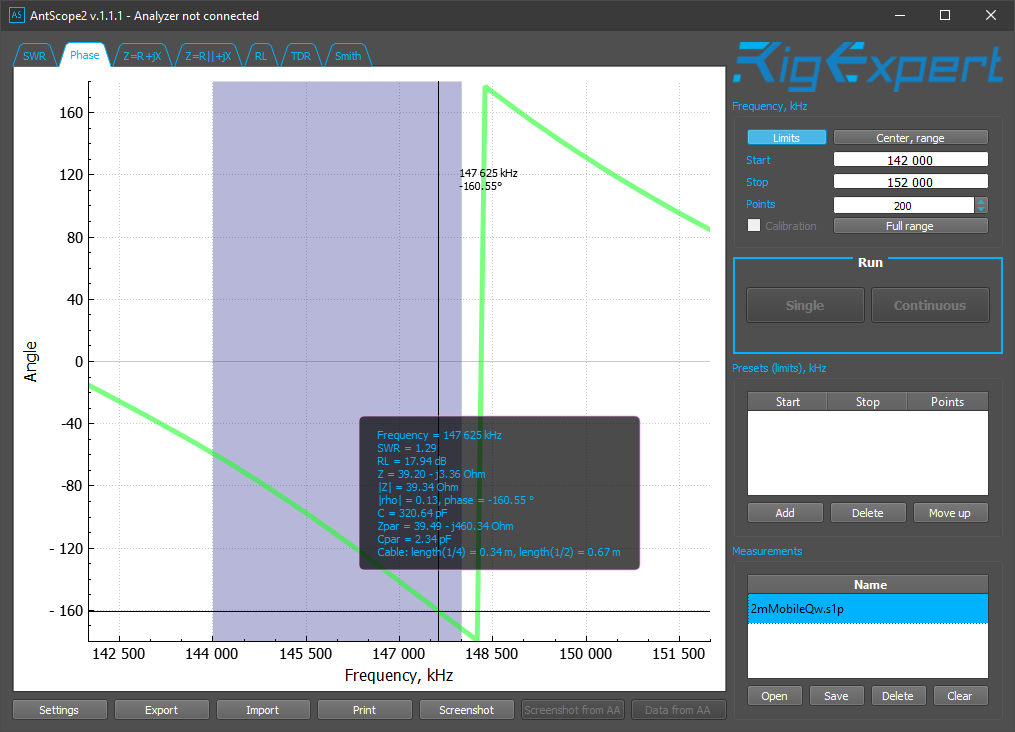
Above is an Antscope2 phase plot for an archived antenna measurement. The measurements are of a 146MHz quarter wave mobile antenna looking into about 4m of RG58C/U cable. We will come back to this. Continue reading Rigexpert Antscope2 – v1.1.1
A recent post by David Knight described dimensional issues with the N connector on his AA-600 and problems with the seller in having it resolved.
Warned of a potential quality issue, I measured my own AA-600.
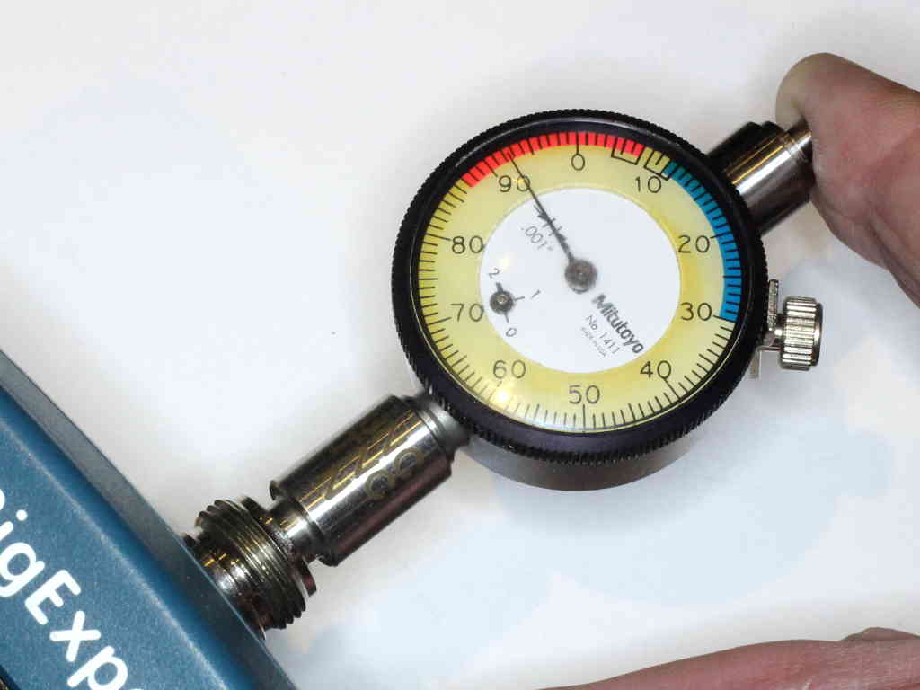
Above, the test of the inner pin forward surface distance from the reference plane on the N jack on the AA-600. The acceptable range on this gauge for the female connector is the red area, and it is comfortably within the red range.

Above is a table of critical dimensions for ‘ordinary’ (ie not precision) N type connectors from Amphenol.
This dimension is important, as if the centre pin protrudes too much, it may damage the mating connector.
Pleased to say mine is ok, FP at 0.192″.
I used a purpose made gauge to check this, but it can be done with care with a digital caliper (or dial caliper or vernier caliper), that is what I did for decades before acquiring the dial gauge above.
At AIM4170 – de-embedding the feed line in remote measurement a set of measurements of a monoband antenna looking from the transmitter were analysed to de-embed the feed line and arrive at the indicated feed point impedance.
This article explores a simple series match to improve the load seen by the transmitter.
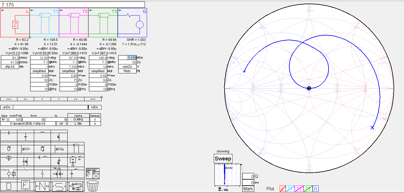
In the Simsmith model above, the estimated feed point impedance is imported into element L, then a series section of lossless 50Ω line to represent the coax in the common mode choke (balun), then a series section of lossless 75Ω to perform the impedance transformation, then a section of 50Ω lossless line to make up the required length to the transmitter. Continue reading AIM4170 – de-embedding the feed line in remote measurement – a simple match
At nanoVNA-H – de-embedding the feed line in remote measurement I recently wrote on a procedure that can be very useful to refer measurements made at the transmitter end of a feed line to the antenna feed point.
A correspondent recently shared an AIM 4170 scan file of his 40m half wave dipole antenna system taken from the transmitter end of the coax and maintaining the common mode current path by bonding the shield of the coax connector to normal connection point on the transmitter.
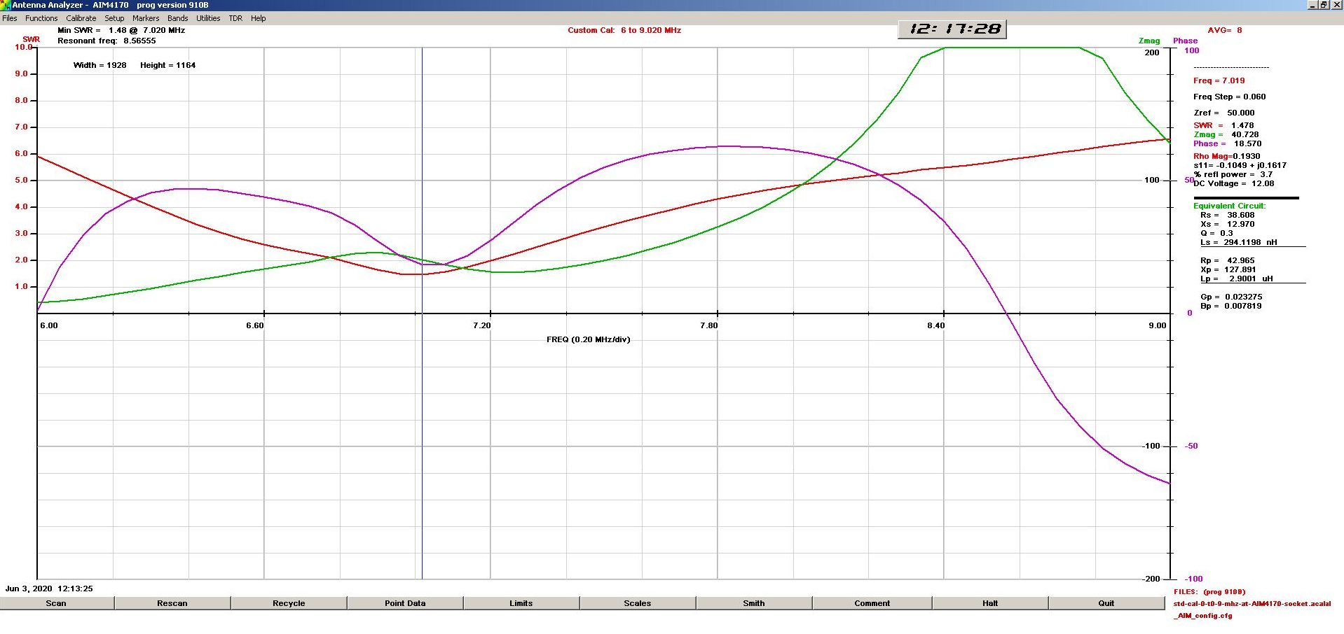
Above is his graphic of the measurement looking into around 23m of RG58 feed line.
It shows the VSWR curve is quite classic in shape, the frequency of minimum VSWR is a little low, and the minimum VSWR is 1.478 which is quite within expectations of such an antenna. Continue reading AIM4170 – de-embedding the feed line in remote measurement
This article is about an inexpensive GU10 230V 7W LED lamp.
Like so much inexpensive Chinese lamp product, it has not markings on the exterior or the lamp (eg voltage, current, power), but the product was sold as 7W and the box had that printed on it.
The lamp failed after less than 100h service, switching on and off intermittently symptomatic of a heat related problem.
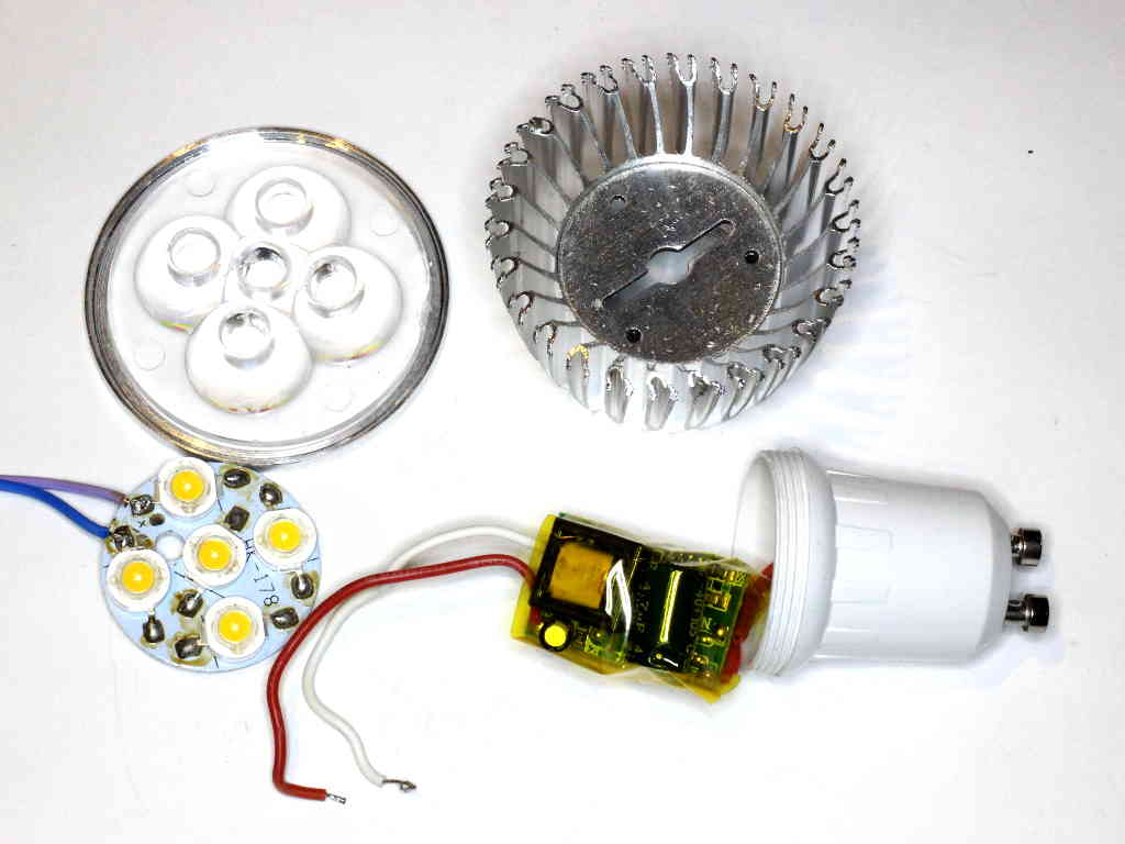
Above is the dismantled lamp. Interestingly the LED driver PCB has “Q-3-5*1W” etched into the board, so presumably it is actually a driver for 5 series 1W white LEDs. So much for the claimed 7W, LED product performance claims are often a fraud, more so when the Chinese are involved. Continue reading LED lamp failure analysis – GU10 230VAC 7W
I was sent a pic of a balun and asked to explain how it works.

With no other detail than the pic, it is difficult to supply a complete answer.
Nevertheless, an analysis of what is presented follows. Continue reading (How) does this balun work?
At nanoVNA-H – measure ferrite transformer I gave an example of using a nanovna to measure loss of a ferrite cored transformer.

Noelec makes a small transformer, the Balun One Nine, pictured above and they offer a set of |s11| and |s12| curves in a back to back test. (Note: back to back tests are not a very reliable test.) Continue reading nanoVNA-H – measure ferrite transformer – Noelec balun