Review of iFIX RT300M v2 LED tester

In other posts on LED luminaires, I identified the need for a test device for LED strings of up to 200+V at currents up to 280mA.

There are quite a number of competitive devices in the market, the article is a review of the iFIX RT300M v2 (which is also sold under other brand names, they may or may not be sourced from the same factory… the Chinese are copyists).


I purchased one of these devices, and it was faulty on delivery. The output voltage never rises above 0.3V, determined to be a hardware fault. With eBay’s intervention, a full refund was obtained without returning the faulty unit which turned out to be a small blessing later.

The v2 RT300M has a button on the top edge of the device. Continue reading Review of iFIX RT300M v2 LED tester

Finding the electrical length of the branches of an N type T – #4

Finding the electrical length of the branches of an N type T – #1 posed a problem, this article looks at one solution.

For convenience, here is the problem.

An interesting problem arises in some applications in trying to measure the electrical length of each branch of a N type T piece.

Let’s make some assumptions that the device is of quality, that the connection from each connector to the internal junction is a uniform almost lossless transmission line of Zo=50Ω. Don’t assume that the left and right branches above are of the same length (though they often are) and we should not assume that the nearest branch is of the same length as the others (and they are often not).

Before we start, we will calibrate the VNA entering the offsets appropriate to the OPEN and SHORT cal parts. In the case of my nanoVNA, measurement above 900MHz is very noisy, so the scan will be 100-890MHz (to avoid a glitch at 900MHz due to harmonic mode switching).

So, the problem is all the uncertain things that connect to the internal T junction. Lets connect a calibration quality 50Ω termination to the left hand port. We now know that the path from the male port to the remaining female port comprises lengths l2 and l1 of low loss 50Ω transmission line with a 50Ω resistor shunting at the junction of l1 and l2. Continue reading Finding the electrical length of the branches of an N type T – #4

Finding the electrical length of the branches of an N type T – #3

Finding the electrical length of the branches of an N type T – #1 posed a problem, this article looks at one solution.

For convenience, here is the problem.

An interesting problem arises in some applications in trying to measure the electrical length of each branch of a N type T piece.

Let’s make some assumptions that the device is of quality, that the connection from each connector to the internal junction is a uniform almost lossless transmission line of Zo=50Ω. Don’t assume that the left and right branches above are of the same length (though they often are) and we should not assume that the nearest branch is of the same length as the others (and they are often not).

Before we start, we will calibrate the VNA entering the offsets appropriate to the OPEN and SHORT cal parts.

So, the problem is all the uncertain things that connect to the internal T junction. Lets connect a calibration quality 50Ω termination to the left hand port. We now know that the path from the male port to the remaining female port comprises lengths l2 and l1 of low loss 50Ω transmission line with a 50Ω resistor shunting at the junction of l1 and l2. Continue reading Finding the electrical length of the branches of an N type T – #3

Finding the electrical length of the branches of an N type T – #2

Finding the electrical length of the branches of an N type T – #1 posed a problem, this article looks at one simple solution.

For convenience, here is the problem.

An interesting problem arises in some applications in trying to measure the electrical length of each branch of a N type T piece.

Let’s make some assumptions that the device is of quality, that the connection from each connector to the internal junction is a uniform almost lossless transmission line of Zo=50Ω. Don’t assume that the left and right branches above are of the same length (though they often are) and we should not assume that the nearest branch is of the same length as the others (and they are often not).

So, the problem is all the uncertain things that connect to the internal T junction. Lets connect a calibration quality 50Ω termination to the left hand port. We now know that the path from the male port to the remaining female port comprises lengths l2 and l1 of low loss 50Ω transmission line with a 50Ω resistor shunting at the junction of l1 and l2. Continue reading Finding the electrical length of the branches of an N type T – #2

Finding the electrical length of the branches of an N type T – #1

An interesting problem arises in some applications in trying to measure the electrical length of each branch of a N type T piece.

Let’s make some assumptions that the device is of quality, that the connection from each connector to the internal junction is a uniform almost lossless transmission line of Zo=50Ω. Don’t that the left and right branches above are of the same length (though they often are) and we should not assume that the nearest branch is of the same length as the others (and they are often not).

Something to keep in mind is that the reference plane for the female connectors is about 9mm inside the T, and you can see the reference plane on the male connector, the nearest end of the shield connection.

With a ruler, the physical length of the left and right female branches looks to be about 13mm, and around 28mm for the male branch… but electrical length will be longer due to an unknown (as yet) deployment of dielectric of unknown type inside the T.

So, put your thinking caps on.

A solution to follow…

Performance of a small transmitting loop with varying height – NEC-5.0

Around 2015 I constructed a series of models exploring the effect of ground proximity on a small transmitting loop (STL).

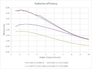
At frequency 7.2MHz, the loop was octagonal with area of 1m^2 equivalent radius a=0.443m, ka=0.067rad, 3.15mm radius copper conductor, lossless tuning capacitor, and centre height above ground (σ=0.007  εr=17 ) was varied from 1.5 to 10m (0.036-0.240λ).

The model series was run in NEC-2, NEC-4.1, NEC-4.2 and NEC-5.0, and the results varied. NEC-4.1 showed serious problems, eg negative input resistance at some heights. The problem was discussed with Burke, and he explained that there was a known problem in NEC-4.1 for small loops near ground, and sent me an upgrade to NEC-4.2 to try with the GN 3 ground model, but that the better solution was in NEC-5 if it was ever released.

NEC-4.2 solved the negative resistance problem, but some issues remained.

With the recent release of NEC-5.0, opportunity arises to compare all four approaches.

(Burke 2019) p45 discusses loop antennas over ground and NEC-5.0.

The plot above of radiation efficiency gives an overall comparison of the different model techniques. (Burke 2019) states Since the mixed-potential solution ensures that the approximated integral of scalar potential around the loop is zero, whether the potential is accurate or not, it might be expected to do better than NEC-4. Continue reading Performance of a small transmitting loop with varying height – NEC-5.0

A mount for the coax relay driver development prototype

I was recently revising the code for the Coax Relay Driver to use a PIC16F1827 chip, and thought a good improvement would be a board that held the prototype electronics and the pulse latching relay together as an assembly.

Above is the design from Fusion360 to be cut from 3mm clear PVC sheet on the CNC router. Continue reading A mount for the coax relay driver development prototype

Adjustable plank refurbishment

I have an adjustable aluminium plank (2.4-3.9m) which after years in the weather, has needed replacement of the plated steel 1/4″ pop rivets used in its construction.

These are strictly for DIY use as long plank spans have not been allowed on work sites for a very long time.

On assurances from the retailer I purchased for $99 a Kincrome CL960 Heavy Duty Hand Riveter Long Arm 525mm (21″) designed for 1/4″ stainless steel poprivets. It failed with less than a dozen rivets with what seems to be a serious design fault (rivet mandrels jam in the inner tube) so it was returned at my cost for a refund. Whilst I have bought lots of Kinchrome product over time, it is when there is a problem one learns a wider lesson.

On assurances from another seller, I then purchased a similar tool on eBay for $36, a tool claimed to work up to 5/16″ stainless steel rivets… so some reserve there?

It failed on the fifth rivet, one of the collets cracked in two and the inside of the chuck sleeve (top right) was grooved suggesting it was not hardened properly. Again, refunded but his time without paying return shipping. Continue reading Adjustable plank refurbishment

Calculation of impedance of a ferrite toroidal inductor – from first principles

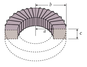
A toroidal inductor is a resonator, though it can be approximated as a simple inductor at frequencies well below its self resonant frequency (SRF). Lets take a simple example, a ferrite toroid of rectangular cross section.

From the basic definition \(\mu=B/H\) we can derive the relationship that the flux density in the core with current I flowing through N turns is given by \(B=\frac{\mu_0 \mu_r N I}{2 \pi r}\). Continue reading Calculation of impedance of a ferrite toroidal inductor – from first principles

NanoVNA – measuring cable velocity factor – demonstration – coax

The article nanoVNA – measuring cable velocity factor discussed ways of measuring the velocity factor of common coax cable. This article is a demonstration of one of the methods, 2: measure velocity factor with your nanoVNA then cut the cable.

Two lengths of the same cable were selected to measure with the nanoVNA and calculate using Velocity factor solver. The cables are actually patch cables of nominally 1m and 2.5m length. Importantly they are identical in EVERY respect except the length, same cable off the same roll, same connectors, same temperature etc.

Above is the test setup. The nanoVNA is OSL calibrated at the external side of the SMA saver (the gold coloured thing on the SMA port), then an SMA(M)-N(F) adapter and the test cable. The other end of the test cable is left open (which is fine for N type male connectors). Continue reading NanoVNA – measuring cable velocity factor – demonstration – coax