Average power of SSB telephony – experimental verification

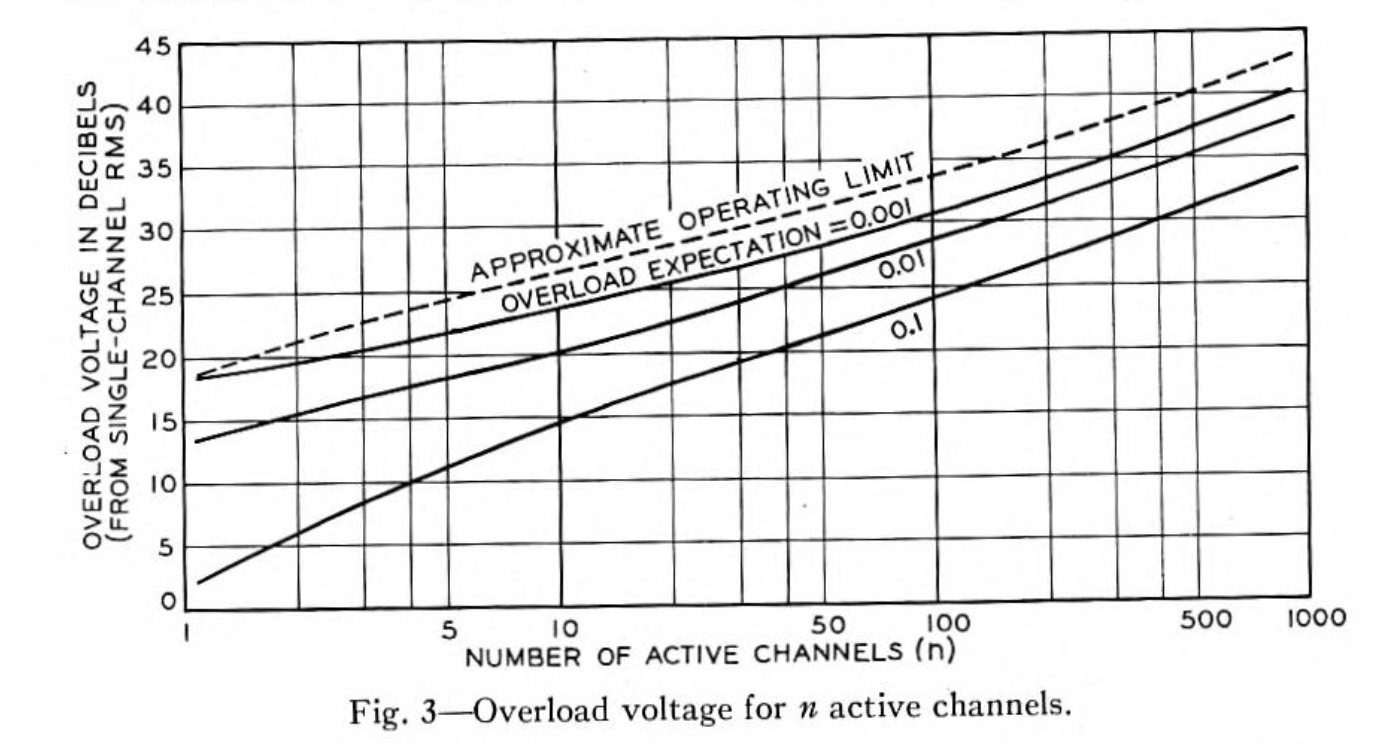
Average power of SSB telephony used 80 year old research by (Holbrook and Dixon 1939) to come up with a ratio of peak voltage to RMS voltage of a voice waveform, and from that derive the ratio PEP/Pav..

(Holbrook and Dixon 1939) explored the subject measuring the voice characteristics of many talkers (as there is variation amongst talkers) to come up with an average characteristic.

Whilst in its day, obtaining instantaneous samples of voice was a challenge, it is trivial today and if you can’t believe the numbers given, try your own experiment (but realise it is for your own voice rather than the general population).

Many modern PC sound applications are capable of the measurement, I will demonstrate it with the feed Windows application Audacity with the stats.ny addin.

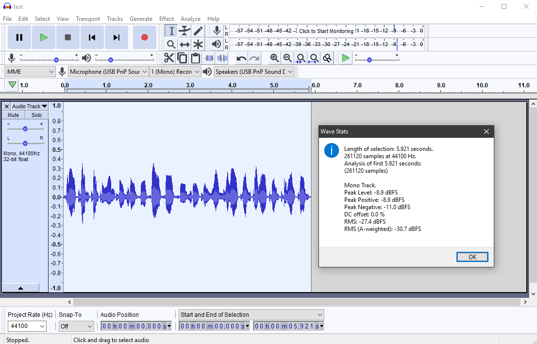
Above is a screenshot of a 6s recording of my voice made without stopping for breath. The statistics window shows a peak of -8.9dBFS and RMS of -27.4dBFS, giving a peak voltage to RMS voltage ratio of 18.5dB. Continue reading Average power of SSB telephony – experimental verification

Power rating of a ferrite cored transformer or balun

Commercial products often have power ratings that bear checking.

There are common some key properties that are relevant:

  • where loss is high, core loss tends to dominate;
  • the specific heat of ferrite is typically quite high;
  • the capacity to dissipate heat is related to many factors.

Continue reading Power rating of a ferrite cored transformer or balun

Average power of SSB telephony

Some components used for SSB telephony need not be capable of handling the Peak Envelope Power (PEP) continuously, many components for instance respond to the average power (Pav) which is quite less. Essentially, components that are subject to voltage breakdown (usually as good as instantaneous) must withstand the PEP, those that heat relatively slowly must withstand Pav.

In estimating the power dissipated in components due to an SSB telephony waveform, a good estimate of the ratio of Average Power (Pav) to Peak Envelope Power (PEP) is very useful.

Long before hams had used SSB, the figure has been of interest to designers of FDM or carrier telephone systems to size amplifiers that must handle n channels of FDM multiplex without overload which would degrade S/N in other channels of the multiplex. The methods are applicable to SSB telephony, it uses the same modulation type and the overload challenges are the same.

(Holbrook and Dixon 1939) gave the graph above which characterises the ratio of instantaneous peak to RMS voltage of voice telephony for different numbers of channels in a multiplex and different expectation of overload or clipping. They recommend a very low probability of clipping at 0.1% to avoid significant intermodulation noise in adjacent channels. Continue reading Average power of SSB telephony

High end VSWR compensation in a ferrite cored RF transformer

The article Estimating the Insertion VSWR in a ferrite cored RF transformer discussed the importance of sufficient magnetising impedance to InsertionVSWR at low frequencies.

Above is a low frequency equivalent circuit of a transformer. Although most accurate at low frequencies, it is still useful for RF transformers but realise that it does not include the effects of distributed capacitance which have greater effect with increasing frequency.

The elements r1,x1 and r2,x2 model winding resistance and flux leakage as an equivalent impedance. Continue reading High end VSWR compensation in a ferrite cored RF transformer

Estimating the Insertion VSWR in a ferrite cored RF transformer

The article Estimating the magnetising or core loss in a ferrite cored RF transformer discussed a first cut approach to determining the minimum magnetising impedance from a core loss viewpoint.

This article considers the effect of magnetising impedance on VSWR.

For medium to high µ cored RF transformers, flux leakage should be fairly low and the transformer can be considered to be an ideal transformer of nominal turns ratio shunted at the input by the magnetising impedance observed at that input winding.

A good indication of the nominal impedance transformation of the combination is to find the VSWR of the magnetising impedance in shunt with the nominal load (eg 50+j0Ω in many cases), and to express this as InsertionVSWR when the transformer is loaded with a resistance equal to n^2*that nominal load (eg 50+j0Ω in many cases). This model is better for low values of n than higher, but it can still provide useful indication for n as high as 8 if flux leakage is low.

Magnetising impedance can be estimated using one of the following calculators, but keep in mind that there are quite wide tolerances on ferrite cores.

Magnetising impedance can be measured (eg with an analyser), but it should be measured with only the measured winding on the core. Did I mention the wide tolerance of ferrites?

Example – FT240-43 3t @ 3.6MHz

You might ask the question is 3t sufficient for the primary of an EFHW transformer that delivers a 50+j0Ω load to a transmitter. Continue reading Estimating the Insertion VSWR in a ferrite cored RF transformer

Estimating the magnetising or core loss in a ferrite cored RF transformer

The article End fed matching – design review and many later ones set out a method of estimating the magnetising or core loss in a ferrite cored RF transformer (such as often used with EFHW antennas).

There are two elements that are critical to efficient near ideal impedance transformation over a wide frequency range, low flux leakage and sufficiently high magnetising impedance. While low magnetising loss is essential for efficiency, it does not guarantee sufficiently high magnetising impedance for near ideal impedance transformation.

Magnetising impedance can be estimated using one of the following calculators, but keep in mind that there are quite wide tolerances on ferrite cores.

Magnetising impedance can be measured (eg with an analyser), but it should be measured with only the measured winding on the core. Did I mention the wide tolerance of ferrites?

Example – FT240-43 3t @ 3.6MHz

You might ask the question is 3t sufficient for the primary of an EFHW transformer that delivers a 50+j0Ω load to a transmitter. Continue reading Estimating the magnetising or core loss in a ferrite cored RF transformer

Exploiting your antenna analyser #30

Quality of termination used for calibration

Some of us use a resistor as a load for testing a transmitter or other RF source. In this application they are often rated for quite high power and commonly called a dummy load. In that role, they usually do not need to be of highly accurate impedance, and commercial dummy loads will often be specified to have maximum VSWR in the range 1.1 to 1.5 (Return Loss (RL) from 26 to 14dB) over a specified frequency range.

We also use a known value resistor for measurement purposes, and often relatively low power rating but higher impedance accuracy. They are commonly caused terminations, and will often be specified to have maximum VSWR in the range 1.01 to 1.1 (RL from 46 to 26dB) over a specified frequency range.

Return Loss

It is more logical to discuss this subject in terms of Return Loss rather than VSWR.

Return Loss is defined as the ratio of incident to reflected power at a reference plane of a network. It is expressed in dB as 20*log(Vfwd/Vref). Continue reading Exploiting your antenna analyser #30

EFHW exploration – Part 2: practical examples of EFHW

EFHW exploration – Part 1: basic EFHW explored the basic half wave dipole driven by an integral source as a means of understanding that component of a bigger antenna system.

The EFHW can be deployed in a miriad of topologies, this article goes on to explore three popular practical means of feeding such a dipole.

The models are of the antenna system over average ground, and do not include conductive support structures (eg towers / masts), other conductors (power lines, antennas, conductors on or in buildings). Note that the model results apply to the exact scenarios, and extrapolation to other scenarios may introduce significant error.

End Fed Zepp with current drive

A very old end fed antenna system is the End Fed Zepp. In this example, a half wave dipole at λ/4 height is driven with a λ/4 600Ω vertical feed line driven by a balanced current source (ie an effective current balun).

Above is a plot of the current magnitudes. The currents on the feed line conductor are almost exactly antiphase, and the plot of magnitude shows that they are equal at the bottom but not so at the top. The difference between the currents is the total common mode current, and it is maximum at the top and tapers down to zero at the bottom. Icm at the top is about one third of the current at the middle of the dipole. Continue reading EFHW exploration – Part 2: practical examples of EFHW

EFHW exploration – Part 1: basic EFHW

The so-called End Fed Half Wave (EFHW) has become very fashionable amongst hams. The idea of end feeding a half wave antenna is hardly new, and there is widespread use of the broad concept… but from online ham discussion, it can be observed that the things are not well understood and indeed, there is magic about them.

A simple model of a simple antenna

This article presents some NEC-4.2 model results for a 7MHz λ/2 horizontal 2mm copper wire at height of λ/4 above average ground.

The model is impractical in a sense that it does not include unavoidable by-products of a practical way to supply RF power to the antenna, but it is useful in providing insight into the basic antenna.

The NEC model has 200 segments, and varying the feed segment gives insight to what happens to feed point impedance.

Above, it can be seen that as the wire is fed closer to the end (segment 1), feed point Z includes a rapidly increase capacitive reactance. Continue reading EFHW exploration – Part 1: basic EFHW

Pawsey Balun – what is it good for?

The Pawsey Balun (or Pawsey Stub) is described as a device for connecting an unbalanced feed to a balanced antenna.

Above is a diagram of a Pawsey Balun used with a half wave dipole (ARRL).

Pawsey Balun on an asymmetric load reported model results in an asymetric dipole antenna, and showed very high common mode feed line current.

Pawsey Balun on an asymmetric load – bench load simulation showed that although the Pawsey balun is not of itself an effective voltage balun or current balun, it can be augmented to be one or the other.

So, you might ask what they do, what they are good for, and why they are used. Continue reading Pawsey Balun – what is it good for?