LNR Precision have announced a small transmitting loop for amateur radio.
This article is a revision to take account of recently updated information published by LNR filling in some of the gaps in their original page. It is encouraging to see better product descriptions and measurement data.
Description
The antenna is described at (LNR Precision 2016).
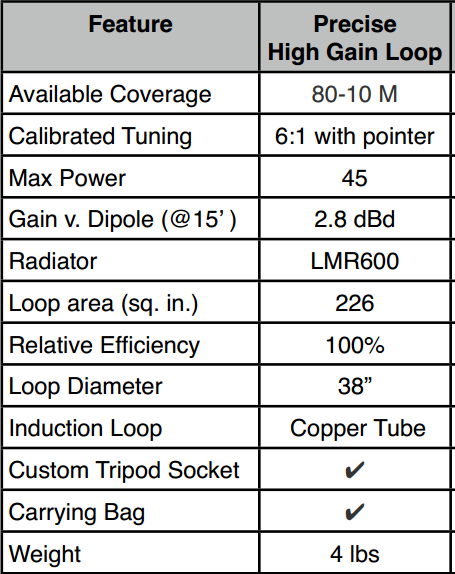
The loop itself appears to be 3/8 Heliax or similar (nominally 9.5mm outer conductor diameter) in a rough circle of 45″ (1.143m) diameter.
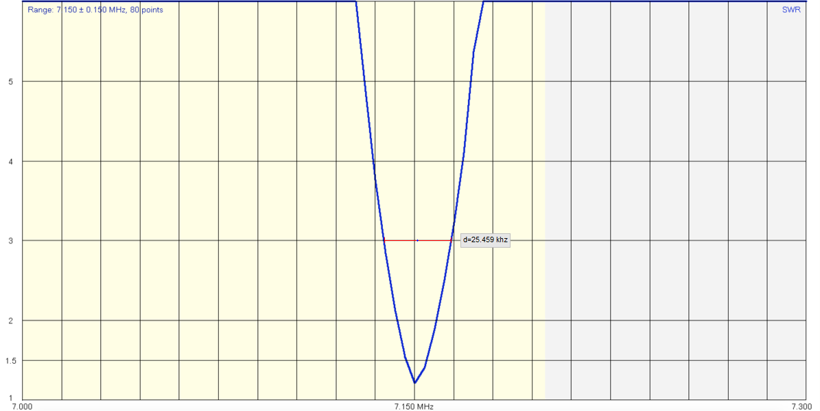
Little information is given of the internals, but the promotional material gives a VSWR curve for a matched antenna at 7.065MHz. To their credit, they give the height above ground and ground type for their tests.
The VSWR=3 bandwidth scaled from the graph is 18kHz.
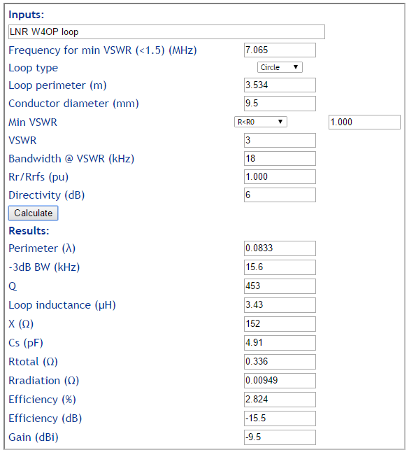
If we assume for a moment that the VSWR measurement was captured at a substantial height above ground, its behavior approaches that of the antenna in free space. Taking the assumption that the published curve is similar to the antenna in free space, we can estimate efficiency based on earlier assumptions. Such antennas very close to ground have a directivity of about 6dB (dependent on ground parameters), and that can be used with efficiency to estimate gain in proximity to ground.

The assumed values and published VSWR curve indicate an antenna system half power bandwidth of 15.6kHz and Q of 453 which implies efficiency of 2.8%.
The actual value for radiation resistance is likely to be with -50-+100% of the free space value used, and that rolls up as an uncertainty of +/-3dB in the calculated efficiency and gain. Continue reading LNR Precision small transmitting loop
Last update: 13th February, 2019, 5:15 AM