Mornhinweg ferrite core measurements – #61

Further to Amidon’s method of rating ferrite inductors and transformers, this article discusses some interesting measurements of ferrite toroids by Manfred Mornhinweg (Mornhinweg 2019).

Mornhinweg ferrite core measurements – #31 discussed his measurements of a #31 suppression sleeve.

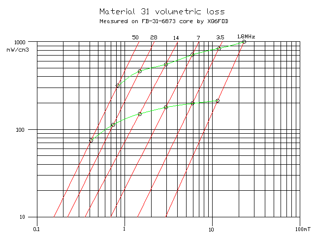
Above are his measurements of a FB-61-6873 sleeve. Essentially there are two measurements at each frequency, and the expected flux density B is in the ratio of approximately 2:1. He has fitted a straight line on a log/log graph to the measurements at each frequency. The similarity of the slopes is not unexpected, and is a tribute to his experiment design, execution and calculations. Continue reading Mornhinweg ferrite core measurements – #61

Using complex permeability to design with Fair-rite suppression products

Fair-rite allocates some of its closed loop ferrite products to two different categories:

  • inductive; and
  • suppression.

Sometimes the same dimensioned cores are available in both categories with different part numbers and possibly different prices, implying some real difference in behavior, eg 5943003801 and 2643803802 are both FT240-43 sized cores.

Material datasheets often contain a note like this from the #43 datasheet:

Characteristic curves are measured on standard Toroids (18/10/6 mm) at 25°C and 10 kHz unless otherwise indicated. Impedance characteristics are measured on standard shield beads (3.5/1.3/6.0 mm) unless otherwise indicated.

I sought to clarify my interpretation of this clause by asking Fair-rite …whether the published material permeability curves / tables apply to suppression product. Can I use the published permeability curves / tables to predict inductor impedance reliably for suppression products?  Fair-rite’s Michael Arasim advised… Continue reading Using complex permeability to design with Fair-rite suppression products

Black body emissivity of ferrite core material

Some of my articles have contained thermal pictures of ferrite cored inductors and transformers.

I have been asked several times recently about the assumed emissivity and the accuracy questioned, I assume this has been discussed online somewhere.

When first measuring ferrites with non-contact thermometers, I performed some experiments to discover whether the default emissivity ε=0.95 applied. It would be convenient if it did, and permit use of some instruments that do not allow adjustment of ε.

In the past, I have compared the reading of non-contact thermometers with several K thermocouple meters and a Thermomelt indicator, and observed insignificant difference (ie less than the variance of repeated measurements).

The following experiment is a thermal pic of a FT240-43 core on the black plastic case of the instrument. The setup has had hours to stabilise thermally.

Above is a combined thermal image and faint visual image. This instrument has only one readout point, and by moving it around, only 0.1° variation was observed between the background and the core. Continue reading Black body emissivity of ferrite core material

Calculate ferrite cored inductor – rectangular cross section – enhancement – chamfered corners

The calculator Calculate ferrite cored inductor – rectangular cross section has until now assumed that the toroid has sharp corners. The corner treatment varies across commercial products, some are burnished which removes very little material, some have a chamfer or bevel, some are radiused. All of these treatments give rise to a very small error in calculated ΣA/l.

The calculator has been revised to include 45° chamfers of a specified length on all four corners. If the chamfer angle differs, the error is very small in the range 30-60°. If the corners are radiused, use the radius as the chamfer length, the error is very small. Continue reading Calculate ferrite cored inductor – rectangular cross section – enhancement – chamfered corners

Jaycar LO1238 ferrite core

Over many years, the Jaycar LO1238 has appeared in some of my projects. I recommended them for a range of applications, particularly applications optimised for low HF.

Above, the core is 35x21x13mm, a mid sized core, two used in my redesign of a commercial balun and implemented by VK4MQ . The mid size limits dissipation, but compactness can be an advantage. The cores sell for less than $4.00 per core and are readily available in Australia. Continue reading Jaycar LO1238 ferrite core

Mornhinweg ferrite core measurements – #31

Further to Amidon’s method of rating ferrite inductors and transformers, this article discusses some interesting measurements of ferrite toroids by Manfred Mornhinweg (Mornhinweg 2019).

Above are his measurements of a FB-31-6873 sleeve. Essentially there are two measurements at each frequency, and the expected flux density B is in the ratio of approximately 2:1. He has fitted a straight line on a log/log graph to the measurements at each frequency. The similarity of the slopes is not unexpected, and is a tribute to his experiment design, execution and calculations. Continue reading Mornhinweg ferrite core measurements – #31

Gauss based ferrite core loss

A reader of Amidon’s method of rating ferrite inductors and transformers wrote to support Amidon’s approach and cited a video by W0QE.

W0QE’s video #80: High Power Balun with #31 Ferrite Material gives some measurements and simulations of a FT240-31 inductor with 11 and 14 turns.

In the video he states:

It turns out that the heating effects in the coil are related to the voltage across the coil only, not the current through the it or anything else.

In fact, there is current flowing through the inductor and that develops a voltage difference across the ends. When we are talking about the self inductance properties, then we are talking about the voltage induced in the inductor as a direct result of the current flowing through the inductance.

Let’s look at his own figures to demonstrate,

Above is his Simsmith model. Let us focus on just the left hand two elements L and R1 (for the 11t inductor) as it is a quite complicated model. L was derived from a measurement of the inductor in a fixture, and to some extent the fixture is captured. Continue reading Gauss based ferrite core loss

Disturbing the thing being measured – coax line

An issue that often arises in online discussions inability to reconcile the VSWR indicated by a transceiver (or possibly an inline VSWR meter) and an antenna analyser.

Is this Segal’s law at play?

There are several common contributors including:

  • faulty, dirty, or not properly mated connectors and cables;
  • VSWR meters that are not accurate at low power levels; and
  • influence of the common mode current path on VSWR.

Continue reading Disturbing the thing being measured – coax line

Amidon’s method of rating ferrite inductors and transformers

I have set out an initial design method for RF inductors and transformers using toroidal ferrite cores and over time I get correspondence drawing my attention to Amidon’s advice, specifically sections 1-35 and 1-36.

Section 1-36 states explicitly that it is applicable to Iron Powder and Ferrite, which is interesting because they are very different materials from a loss point of view.

Basically, their method depends on a maximum safe value for peak flux density.

They give an expression for peak flux density \(B_{max}=\frac{10^8E }{4.44 A_e N F}\) and the following table of design limits for Bmax.

Note that the table and formula are independent of ferrite mix type (though they do mention that “these figures may vary slightly according to the type of material being used.” Continue reading Amidon’s method of rating ferrite inductors and transformers

Quantifying performance of a simple broadcast receive system on MF

I see online discussions struggling to try to work out if a receiving system is sufficiently good for a certain application.

Let’s work an example using Simsmith to do some of the calculations.

Scenario:

  • 20m ground mounted vertical base fed against a 2.4m driven earth electrode @ 0.5MHz;
  • 10m RG58A/U coax; and
  • Receiver with 500+j0Ω ohms input impedance and Noise Figure 20dB.

An NEC-4.2 model of the antenna gives a feed point impedance of 146-j4714Ω and radiation efficiency of 0.043%, so radiation resistance \(Rr=146 \cdot 0.00043=0.0063\).

Above, the NEC antenna model summary. Continue reading Quantifying performance of a simple broadcast receive system on MF