Exploiting your antenna analyser #11

Backing out transmission line

Often we make measurements through a section of transmission line, and the measurements are wrt the reference plane, which for many analysers is the connector on the instrument.

Some analysers, or their associated software allow the effects of the transmission line to be backed out.

Screenshot - 17_01_16 , 09_16_18

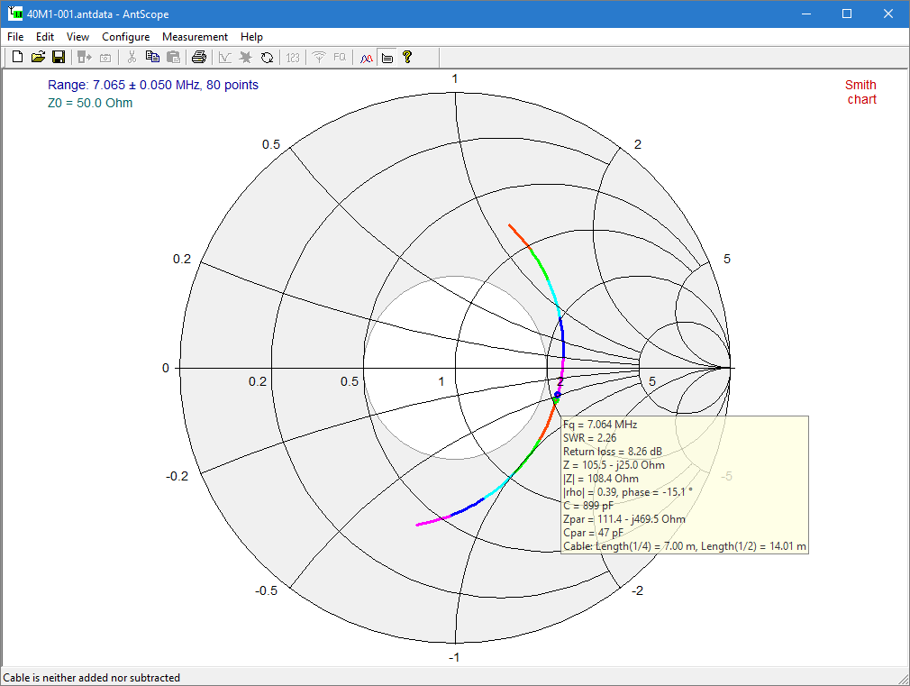
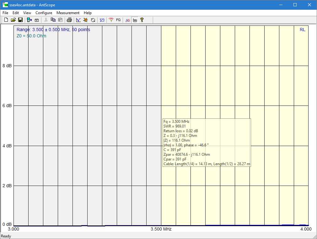
Above is a Smith chart view of measurement of a test antenna through some length of RG58. The antenna will have R<50Ω at minimum VSWR, so the angle of the complex reflection coefficient Γ will be close to 180° at the feed point. Antscope uses a different notation, but shows here the angle at the point of measurement to be -15.1°, so we need to increase it by 180–15.1=195.1°, which will take about half that electrical length of line, 97.6°. From TLLC, I calculate the length involved is 7.6m of RG58, which is an estimate that gives a starting point for backing out the cable. Continue reading Exploiting your antenna analyser #11

Exploiting your antenna analyser #10

Measuring an RF inductor

This article walks through practical measurement of a ferrite toroidal inductor using an antenna analyser.

To be relevant practically, lets use an example from N4SPP’s end fed wire antenna on 3.6MHz. His coupling transformer uses a two turn winding on an FT240-43 core for the nominal 50Ω connection to the antenna system.

We could calculate the impedance of this winding using one of the plethora of online and desktop inductance calculators, but lets first fetch the data from the manufacturer.

Screenshot - 29_12_2015 , 11_05_50 AM

A simple statistic that is widely used is Al, and above, Fair-rite gives Al=1075nH +/-20%. Note that although they give a tolerance of +/-20%, it is not uncommon that manufactured product has greater error, they may have optimistically quoted the standard deviation and it is easy to fall outside that (37% chance). Continue reading Exploiting your antenna analyser #10

Exploiting your antenna analyser #9

Disturbing the thing you are measuring

In all measurements, we need to be careful that the measurement does not disturb the thing being measured.

This article explores an example where the instrument measurements appear wrong.

The story starts with a mobile antenna that the transceiver indicates has very high VSWR over the 40m band, though starts to decrease towards 7.350MHz.

To assist in problem identification / tuning, the antenna connector is disconnected from the radio and connected to the AA-600 analyser and a sweep taken.

Screenshot - 16_12_2015 , 5_03_16 PM

Above is the sweep, but it is quite inconsistent with the transceiver’s VSWR meter readings. The plot above looks good, a little adjustment of the tip would get it down to 7.060… but the transceiver does not see it that way. Continue reading Exploiting your antenna analyser #9

Exploiting your antenna analyser #8

Finding resistance and reactance with some low end analysers

Clip 010

There are some analysers on the market that do not display reactance X or even magnitude of reactance |X| and possibly resistance, but do display VSWR and magnitude of impedance |Z|. Continue reading Exploiting your antenna analyser #8

Exploiting your antenna analyser #7

Application to a loaded mobile HF whip

This article explores application of an antenna analyser to a helically loaded 7MHz mobile whip that has an adjustable length tip for tuning.

The task at hand is to ‘tune’ the antenna to a desired operating frequency.

The analyser used is a Rigexpert AA-600, but the article deals more generally with analyser features.

Initial measurement and interpretation

Screenshot - 11_12_2015 , 3_02_53 PM

Above is a plot of R, X, and |Z| measured at the cable connector that plugs onto the transmitter. Ignore |Z|, it is irrelevant and confusing but unfortunately a ‘feature’ of the Rigexpert software that cannot be disabled. Continue reading Exploiting your antenna analyser #7

Exploiting your antenna analyser #6

Shunt match

Now one of the methods that is often used to transform the impedance of an antenna to suit a 50Ω feed line is the shunt match.

Lets explore that with our test jig reconfigured.

Connect up the two line sections in cascade from the analyser, and terminate it with the two 50Ω loads on the tee piece. Don’t worry too much about what we have in terms of implementation, it provides a load to the analyser that presents a similar scenario to shunt matching a loaded short monopole.

So, measure the input impedance around 21MHz.

Screenshot - 10_12_2015 , 1_51_20 PM

Above is a scan with the Rigexpert AA-600 from around 21MHz. Ignore the |Z| line, it is irrelevant and confusing but I cannot switch it off, a shortcoming of the software.

What we are exploring is that as we change frequency, the parallel equivalent resistance changes at 21.275MHz above, it equals 50Ω. The full parallel equivalent is 50Ω//-j77.3. So, if we were to make a small inductor of 77.3Ω reactance (L=X/(2*pi*f)=580nH) and connect it in shunt, the resulting impedance will be 50+j0Ω. Continue reading Exploiting your antenna analyser #6

Exploiting your antenna analyser #5

Measure MLL using the Rin where X=0

Another method of estimating Matched Line Loss (MLL) from measurement is using the input resistance of a section that is an odd or even number of quarter waves in electrical length.

I say estimate because this method depend on an assumption of the value of Zo, and using purely real nominal Zo introduces some error.

The required length can be approximated by fining a frequency where X passes through zero. Again, this method is an approximation.

Simple formula

There is a simple formula published in many ham handbooks:

MLL≈8.686*Rin/Zo/length dB/unitlength

It is, a discussed at Measuring matched line loss, a crude approximation (and should be written with ≈ rather than =).

Better formula

A better formula is one I developed though it may not be novel:

MLL=-10log|(Rin-Zo)/(Rin+Zo)|/length dB/m

It is exact, but there is error introduced in using nominal Zo.

In practice

Low Z measurement

Lets measure Zin of our 4m o/c line section, and find the lowest frequency where X passes through zero, and note the value of Rin.

Screenshot - 10_12_2015 , 2_01_52 PM

Above is a wide sweep, the frequency we want to focus on is around 13MHz. Continue reading Exploiting your antenna analyser #5

Exploiting your antenna analyser #4

Measure MLL using the half ReturnLoss method

Again in the theme of measuring something known, let us determine the matched line loss (or normally quoted attenuation) of our cable at 3.5MHz.

To make the measurement, just connect the two test line sections used in the earlier articles in this series in cascade with a joiner, and one end on the instrument, other end open circuit, and measure ReturnLoss.

Most analyser manuals and lots of helpful articles in journals and handbooks will tell you that MLL=RL/(2*length) where RL is the ReturnLoss of an open circuit or short circuit line section (the only requirement is that the ρ=1 at the line end).

Screenshot - 10_12_2015 , 8_20_14 AM

Wow, that is so low, and using the traditional formula:

MLL=0.02/(2*4)=0.0025dB/m.

Of course we are measuring way low in the instrument’s capability and there is some considerable uncertainty… but when we consult a good transmission line loss calculator, we expect around 0.029dB/m… that is 12 times what we measured. Continue reading Exploiting your antenna analyser #4

Exploiting your antenna analyser #3

The sign of reactance

At Exploiting your antenna analyser #2, the matter of determining sign of reactance was mentioned.

If you have an analyser that does not measure the sign of reactance, this information should be important to you.

Screenshot - 9_12_2015 , 8_24_15 AM

Above is a Smith chart plot of  measurements from 15MHz to 25MHz.

One can see that the locus of Zin on the Smith chart forms an arc, and the points on the arc rotate clockwise about the arc centre with increasing frequency. Continue reading Exploiting your antenna analyser #3

Exploiting your antenna analyser #2

Reconciling the single stub tuner results

So having found that the length of the RG58 lines sections are both 1.98m (approximately 2m), let’s try to reconcile measurement and prediction of Zin at 9MHz.

The examples discussed in this series of articles are designed for the test jig as described at Exploiting your antenna analyser #1 with a pair of nominally 2m length RG58 patch leads, a pair of 50Ω loads and some tee pieces and adapters to connect it all up. If you duplicate it, you will experience the same learning opportunities (the examples are structured). If you presume to redesign the experiment, your outcome will probably be different.

Before you read on, take a measurement of Zin at 20MHz and write down the impedance value. Do whatever you do to determine the sign of the reactance. If your instrument displays the sign properly, use it, otherwise use the method in your user manual or whatever wisdom you trust.

Done that? If so, read on… Continue reading Exploiting your antenna analyser #2