The oft asked question of how much an LNA improves a 70cm weak signal station – Rules of Thumb

The article The oft asked question of how much an LNA improves a 70cm weak signal station solicited some comment on optimal configurations. This article deals with the notion / Rule of Thumb that optimal LNA gain is just sufficient to offset line losses.

This article explains with graphs the relationship between Signal / Noise degradation (see Signal to noise degradation (SND) concept) and LNA gain in the configurations discussed in the original article. See The oft asked question of how much an LNA improves a 70cm weak signal station for documentation of the scenario assumptions.

The critical value for SND is a personal choice, but for the purpose of this discussion, let’s choose 1dB. That is to say that the S/N at the receiver output is less than 1dB lower than the ultimate that could achieved with the antenna system given the external noise environment.

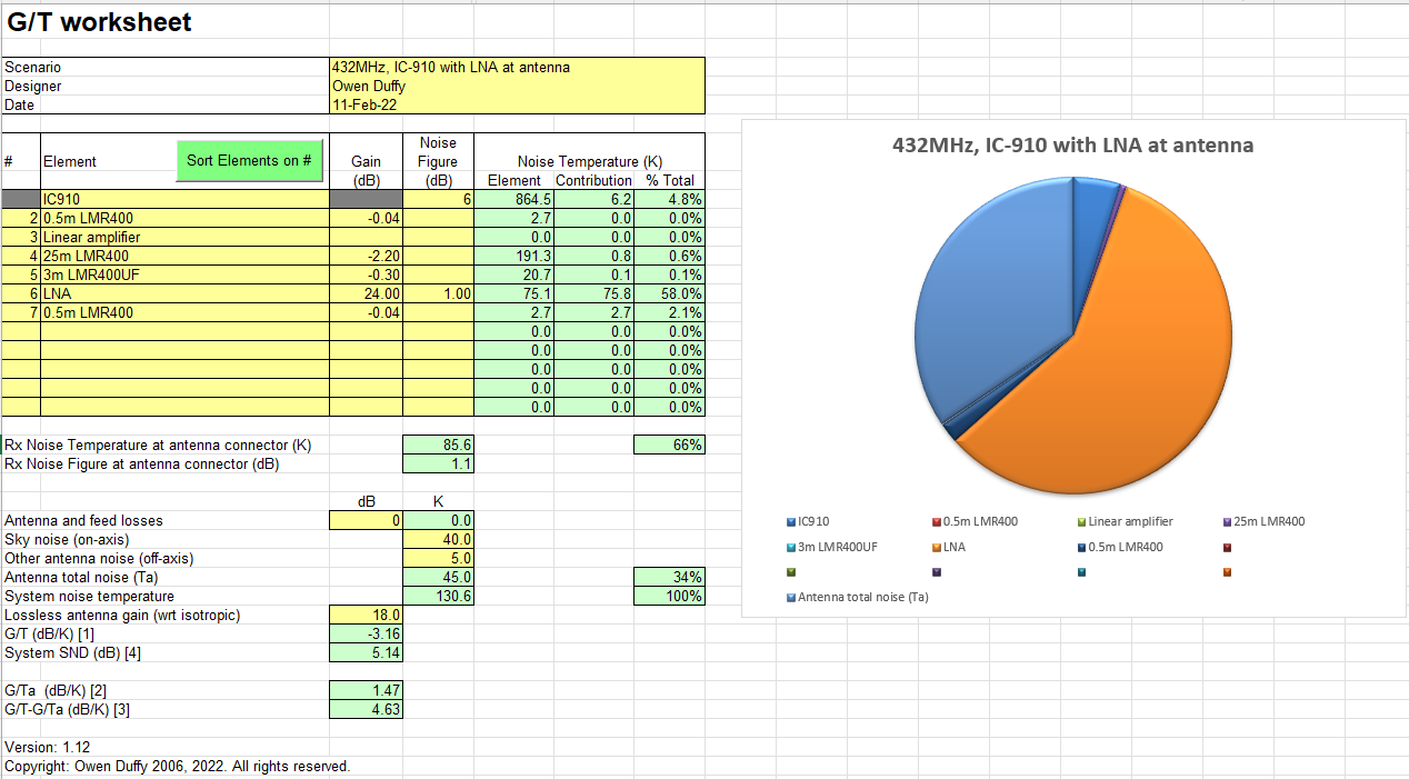
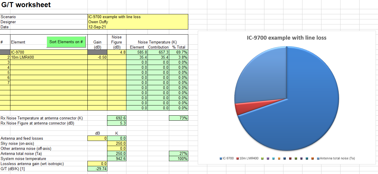
The total line loss in the example configurations was 2.6dB. The model assumes that LNA Noise Figure is independent of LNA Gain, though in the real world, there is typically some small dependence.

Often the choice of LNA Gain drives the choice of a single stage or two stage LNA, which has cost implications.

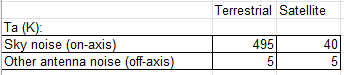
Terrestrial external noise – 495+5K

Above is a chart showing SND vs LNA Gain. It can be seen that as LNA gain is increased, SND improves rapidly with a knee around 15dB LNA gain above which SND improvement is slower. Continue reading The oft asked question of how much an LNA improves a 70cm weak signal station – Rules of Thumb

The oft asked question of how much an LNA improves a 70cm weak signal station

A recent online post seeking opinions on the chap’s 70cm weak signal configuration is an interesting subject for study, and one that should be of interest to many weak signal DXers.

This article focusses on just one question in a quite similar configuration, what is the advantage given by the LNA?

Study configuration

The scenario will be evaluated for both terrestrial and satellite paths.

Above is the assumed ambient noise environment, it has great bearing on the results. More on that later. Continue reading The oft asked question of how much an LNA improves a 70cm weak signal station

Ambient noise measurement using whip on vehicle – #2 – active antenna electronics

This article continues from Ambient noise measurement using whip on vehicle – #1 – estimate Antenna Factor with a case study for the active antenna electronics.

For this discussion, I will use the amplifier developed at A high performance active antenna for the high frequency band, but applied to the antenna described at Ambient noise measurement using whip on vehicle – #1 – estimate Antenna Factor.

Let’s assume that the antenna + amplifier will be used with a HF receiver with Noise Figure 6dB, Teq=864.5K.

From (Martinsen 2018) Fig 3.8, the amplifier internal noise at the output terminals is -118dBm in 100kHz @ 3.5MHz. That implies that the amplifier Noise Temperature is 857.93K. The amplifier has 6.4dB voltage gain which needs to be subtracted from the AF calculated for unity gain (at the amplifier input terminals). Continue reading Ambient noise measurement using whip on vehicle – #2 – active antenna electronics

Ambient noise measurement using whip on vehicle – #1 – estimate Antenna Factor

This article lays out a method for estimating the Antenna Factor of a short vertical mounted on the roof of a vehicle for use with a high impedance amplifier for ambient noise measurement at 3.5MHz.

Ambient noise is commonly dominated by man made noise, and it often arrives equally from all directions. For measurement of such noise, the captured power depends on average antenna gain, and so the calculations below focus on gain averaged over the hemisphere.

Antenna Factor is often very convenient for field strength measurement as it relates the external E field strength to the receiver terminal voltage given a certain antenna (system). In fact, given a short vertical terminated by a high impedance amplifier, Antenna Factor is often fairly independent of frequency over several octaves of frequency. Continue reading Ambient noise measurement using whip on vehicle – #1 – estimate Antenna Factor

Do I ‘need’ a masthead preamp to work satellites on 2m? – G/T vs G/Ta

A reader of Do I ‘need’ a masthead preamp to work satellites on 2m? – space noise scenario has written to say he does not like my comments on the hammy adaptation of G/T.

Above is an archived extract of a spreadsheet that was very popular in the ham community, both with antenna designers and sellers and end users (buyers / constructors). It shows a column entitled G/T which is actually the hammy calculation. The meaning possibly derives from (Bertelsmeier 1987), he used G/Ta.

Ta is commonly interpreted by hams to be Temperature – antenna. It is true that antennas have an intrinsic equivalent noise temperature, it relates to their loss and physical temperature and is typically a very small number. But as Bertelsmeier uses it, it is Temperature – ambient (or external), and that is how it is used in this article.

Let’s calculate the G/Ta statistic for the three scenarios in Do I ‘need’ a masthead preamp to work satellites on 2m? – space noise scenario.

Base scenario

Above is a calculation of the base scenario, G/T=-29.74dB/K.

Also shown in this screenshot is G/Ta=-23.98dB/K. Continue reading Do I ‘need’ a masthead preamp to work satellites on 2m? – G/T vs G/Ta

Do I ‘need’ a masthead preamp to work satellites on 2m? – terrestrial noise scenario

Do I ‘need’ a masthead preamp to work satellites on 2m? – space noise explored a scenario for a high gain antenna pointed skywards. This article explores the case of a omni antenna which basically captures ‘terrestrial’ noise.

Base scenario is a low end satellite ground station:

  • 144MHz;
  • terrestrial noise (satellite with omni antenna);
  • IC-9700, assume NF=4.8dB;
  • omni antenna;
  • 10m of LMR-400.

Continue reading Do I ‘need’ a masthead preamp to work satellites on 2m? – terrestrial noise scenario

Do I ‘need’ a masthead preamp to work satellites on 2m? – space noise scenario

A question asked online recently provides an interesting and common case to explore.

Base scenario is a low end satellite ground station:

  • 144MHz;
  • satellite;
  • IC-9700, assume NF=4.8dB;
  • high gain (narrow beamwidth antenna);
  • 10m of LMR-400.

Continue reading Do I ‘need’ a masthead preamp to work satellites on 2m? – space noise scenario

Comparing sensitivity figures of an AM receiver and SSB receiver

Receiver sensitivity is commonly given as some signal level, say in µV, for a given Signal to Noise ratio (S/N), say 10dB. For AM, the depth of sinusoidal modulation is also given, and it is usually 30%. In fact these are power ratios in the context of and some nominal reference receiver input impedance.

In fact what is commonly measured is Signal + Noise to Noise ratio, and of course this ratio is one of powers. For this reason, specifications often give (S+N)/N.

This article discusses those metrics in the context of ‘conventional’ receivers and introduces the key role of assumed bandwidth through the concept of Equivalent Noise Bandwidth..

Let’s consider the raw S/N ratio of an ideal AM detector and ideal SSB detector.

Raw Signal/Noise

AM


Above is a diagram of the various vector components of an AM signal with random noise, shown at the ‘instant’ of a modulation ‘valley’. The black vector represents the carrier (1V), the two blue vectors are counter rotating vectors of each of the sideband components, in this case with modulation depth 30%, and the red vector is 0.095V of random noise rotating on the end of the carrier + sideband components. Continue reading Comparing sensitivity figures of an AM receiver and SSB receiver

Quantifying performance of a simple broadcast receive system on MF

I see online discussions struggling to try to work out if a receiving system is sufficiently good for a certain application.

Let’s work an example using Simsmith to do some of the calculations.

Scenario:

  • 20m ground mounted vertical base fed against a 2.4m driven earth electrode @ 0.5MHz;
  • 10m RG58A/U coax; and
  • Receiver with 500+j0Ω ohms input impedance and Noise Figure 20dB.

An NEC-4.2 model of the antenna gives a feed point impedance of 146-j4714Ω and radiation efficiency of 0.043%, so radiation resistance \(Rr=146 \cdot 0.00043=0.0063\).

Above, the NEC antenna model summary. Continue reading Quantifying performance of a simple broadcast receive system on MF