Much is written about antenna system balance, this article looks at balance issues with the very common ATU configuration that uses a Ruthroff 4:1 voltage balun to adapt coax transmitter output to two wire open feed line. This type of balun is employed in most ham market ATUs that contain an integral balun.
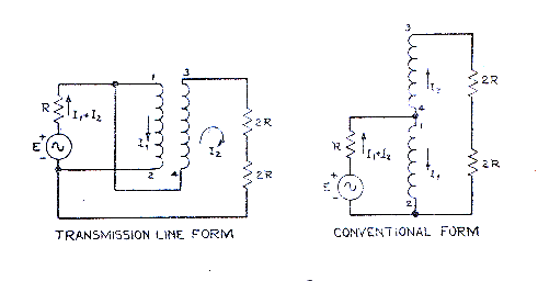
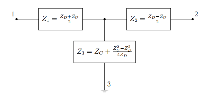
 Above is Ruthroff’s equivalent circuit, Fig 3 from his paper (Ruthroff 1959).
If one looks carefully at the transmission line form, there is effectively a two wire line wound into a helix (usually on a magnetic core) and connected from the unbalanced source to one half of the load inverting the connection for the necessary phase reversal.
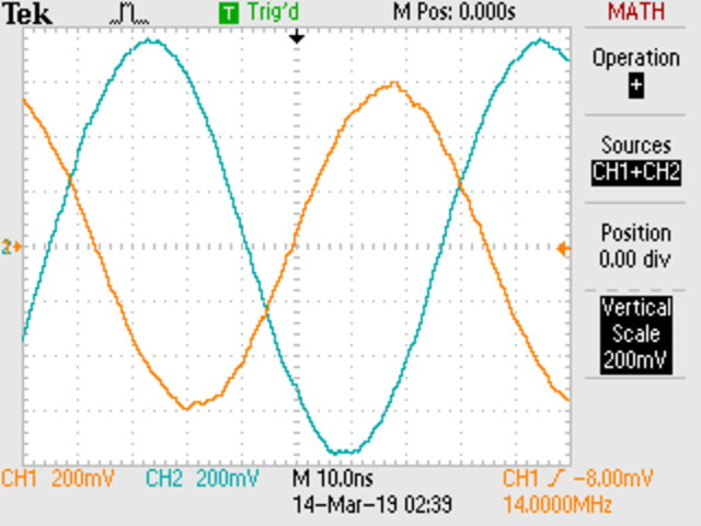
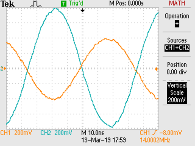
Ideally, Vout of this line is equal to Vin, ie Vout/Vin should be 1∠0°. That is unlikely as it implies a zero length transmission line which provides the decoupling of the phase inverting line.
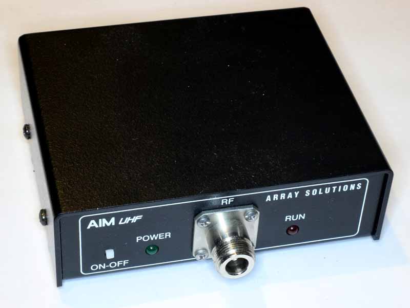
This article looks at the Ruthroff 4:1 balun balance using the very popular MFJ-949E as an example.

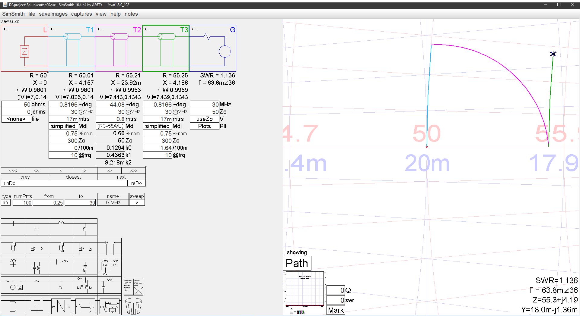
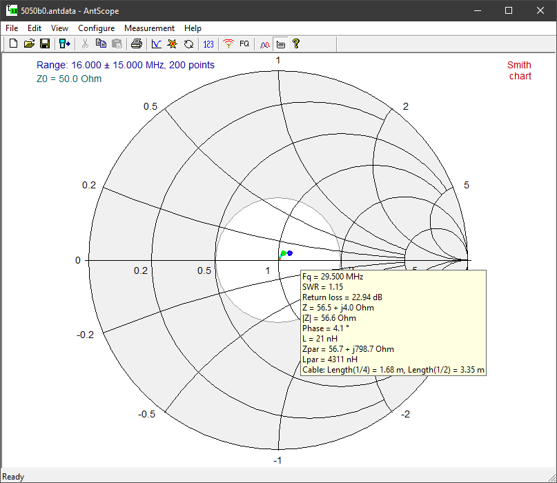
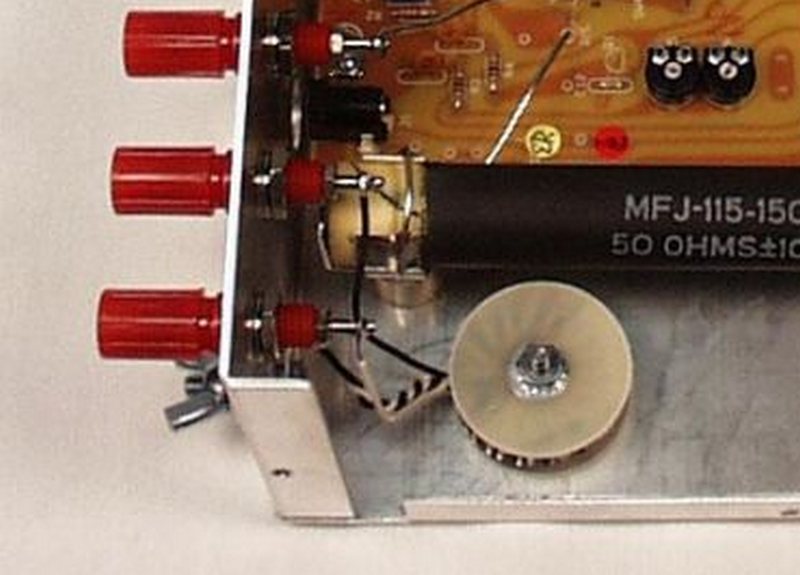
Above is a pic of the MFJ-949E Ruthroff 4:1 balun. The transmission line is not uniform, but let’s make an approximation to predict its behavior with a centre tapped 100Ω load, the centre of which is connected to the ground terminal. Continue reading Voltage symmetry of practical Ruthroff 4:1 baluns
Last update: 9th March, 2019, 6:52 AM