RF transmission lines – quite old art

From time to time I see online discussion about determining matched line loss (MLL) from Return Loss.

Something like 150 years ago a self educated genius thought about the problem of ‘smearing’ of telegraph signals in submarine cables and developed a model for the behavior of transmission lines that remains a very good model today. (The guy’s day job was as a telegraphist.)

He needed to develop new mathematics and new concepts like reactance, and he did this in the face of recognised engineers of the day dismissing the ideas.

The smearing problem was different propagation speed of the fundamental and harmonic components of the telegraphy waveform, he referred to it as distortion and in terms of his RLGC transmission line model he defined the requirements for a “Distortionless Line”. Zo for a Distortionless line is a purely real number, and a Lossless Line is a special case of a Distortionless Line. Continue reading RF transmission lines – quite old art

Windowed ladder line – single core CCS 21% IACS

There is some evidence that the common 1.024mm (#18) single core CCS windowed ladder line advertised as 30% IACS conductivity supplied recently may be closer to 21%. This is based solely on comparison of measured DC resistance with specification, but that is a strong hint that the copper cladding is less than specification.

Theoretical prediction

This article presents a theoretical prediction based o A model of current distribution in copper clad steel conductors at RF of the matched line loss (MLL) at 1.8MHz.

The assumption is a 1.024mm steel cored conductor with 30.7µm copper cladding.

Above is a plot of the predicted current magnitude and phase distribution in the conductor. Continue reading Windowed ladder line – single core CCS 21% IACS

Radcom Feb 2019 “cable balun” – comment on Radcom “The last word” letter

At Radcom Feb 2019 “cable balun” and
Radcom Feb 2019 “cable balun” – a deeper look I wrote about a novel balun by K3MT.


Fig 1

Above is a diagram of the so-called “cable balun”.

My evaluation essentially showed that it was not effective in an example practical scenario where one might want to use a balun, and that of itself, it was not likely to significantly reduce common mode current in most scenarios.

Radcom Mar 2020 published  a letter in “The last word” from the author defending the device citing a NEC model of one scenario, curiously though without explanation, a different topology to the diagram above from the original article. Note also that it is a structure in free space with no discussion of how that is relevant to real world antennas near ground. Continue reading Radcom Feb 2019 “cable balun” – comment on Radcom “The last word” letter

W551 CCS windowed ladder line – a guide to low end loss

At Simsmith bimetal line type – a comparison around the first MLL minimum I reported calculated matched line loss vs cladding depth for a single core copper clad steel conductor in a feed line such as Wireman 551.

The common assumption is that as frequency is reduced, so is loss, and at low frequencies loss is roughly proportional to square root of frequency.

That model is for homogenous conductors with well developed skin effect and is not applicable to the CCS line under discussion.

Above is a plot for various cladding depth on a 1.024mm (#18) 30% IACS (67µm cladding) CCS conductor at 1.8MHz where skin depth δ is 49µm. MLL is minimum around cladding depth 100µm or 2δ. Continue reading W551 CCS windowed ladder line – a guide to low end loss

nanoVNA-H – continuing USB-C woes

I have reported issue with the USB-C plug / socket arrangement on the nanoVNA-H.

It is very sensitive to any jiggling of the cable or connector, causing a reset of the nanoVNA which almost always means lost work.

Having tried a number of different cables that have worked reliably on other devices, I initially thought there was little difference.

I did have a good response to jetting plug and jack with IPA, but the effects are shortlived.

This brings me to consider whether the connector is degrading making debris that makes for unreliable contact, or whether this is too little spring pressure in the plug.

Above is a view into the supplied USB-C plug. The pic has been taken with care to line up the die parting marks at back and front of the connector, so the view is in line with the connector axes. Continue reading nanoVNA-H – continuing USB-C woes

Simsmith bimetal line type – a comparison around the first MLL minimum

At Simsmith bimetal line type I reported an experiment with Simsmith’s experimental bimetal line type.

The details of the model are a little sketchy, I was interested in how it modelled the phase of the layer currents, or if you like the implied velocity of propagation of the EM wave in the conductor.

Again the model is of a copper clad steel conductor, but tweaked a little to fit the apparent limit to the number of layers modelled in Simsmith, it is 1mm diameter, 500 layers (1µm per layer).


Above is the model with cladding thickness set to 20% or 100µm. Continue reading Simsmith bimetal line type – a comparison around the first MLL minimum

Measuring coaxial cable loss by reflection with a directional wattmeter

At Measuring coaxial cable loss by reflection with a VNA I discussed measuring terminated coax cable loss by reflection with an VNA, and you might ask the question can it be done with a scalar network analyser, return loss bridge, or directional wattmeter, all of which provide a measure of the amplitude of reflection wrt some reference impedance.

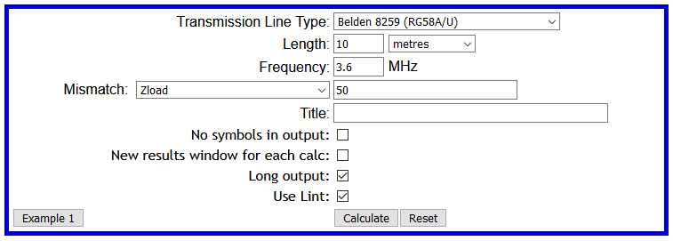
This article explores using a Bird 43 directional wattmeter to measure line loss in a similar scenario. We will use 6m of Belden 8359 (RG58A/U) @ 3.6MHz.

Expectation

A short digression, what is the specification Matched Line Loss (MLL) at 3.6MHz? Using TLLC we get 0.171dB, that is our expectation.

Return Loss of SC section

(Bird 2004) gives the following advice.

Line loss using open circuit calibration: The high directivity of elements can be exploited in line loss measurements, because of the equality of forward and reflected power with the load connector open or short circuited. In this state the forward and reflected waves have equal power, so that φ = 100% and ρ = ∞.
Open circuit testing is preferred to short circuit, because a high quality open circuit is easier to create than a high quality short. To measure insertion loss, use a high quality open circuit to check forward and reverse power equality, then connect an open-circuited, unknown line to the wattmeter. The measured φ is the attenuation for two passes along the line (down and back). The attenuation can then be compared with published data for line type and length (remember to halve Ndb or double the line length to account for the measurement technique).

This also contains the hoary old chestnut that a good OC termination is hard to achieve, but this author’s experience of measurement with modern VNAs is not consistent with Bird’s assertion.

So lets do a theoretical simulation of the Bird 43 applied to this problem.

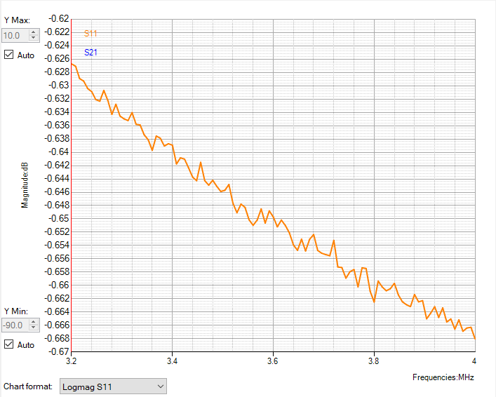
Lets say we connect a source to the line section with a short circuit (SC) termination, and that the Bird 43 reads Pfwd=90W, and we read Pref=78W, we can calculate return loss \(RL=10 \cdot log_{10}\frac{P_{fwd}}{P_{ref}}=0.65dB\), so RL/2=0.65/2=0.325dB.

Continue reading Measuring coaxial cable loss by reflection with a directional wattmeter

Measuring coaxial cable loss by reflection with a VNA

At Measuring coaxial cable loss with a voltmeter I discussed measuring terminated coax cable loss with an RF voltmeter, and it had some real practical limitations.

This article explores using a nanoVNA to measure line loss in a similar scenario. We will use 6m of Belden 8359 (RG58A/U) @ 3.6MHz.

The same technique could be used with a quality antenna analyser.

Expectation

A short digression, what is the specification Matched Line Loss (MLL) at 3.6MHz? Using TLLC we get 0.171dB, that is our expectation.

Return Loss of SC section

A common method proposed is to measure Return Loss (RL) of a section with load end RL=0dB and halve it. Many experts advise that the section should be terminated in a short circuit (S) because short circuits are more reliable than open circuits. So let’s get cracking.

Above is measured |s11| using a nanoVNA with recent OSL calibration from 1-30MHz. |s11| @ 3.6MHz is by eye -0.651dB, RL=-|S11|, so RL/2=0.651/2=0.325dB. Continue reading Measuring coaxial cable loss by reflection with a VNA

Measuring coaxial cable loss by transmission measurement with a directional wattmeter

The article Measuring coaxial cable loss with a voltmeter discussed some pitfalls of that measurement method, starting with the influence of theoretical error in actual Zo at lower frequencies.

You might expect that using a directional wattmeter has exactly the same problems because as many online experts advise, at the end of the day they are just a voltmeter.

They are wrong, a Bird 43 might use a half wave detector driving a d’Arsonval meter and you might regard that to be a voltmeter, but the RF signal it measures is a combination of samples of forward and reflected waves wrt to its calibration impedance (usually 50+j0Ω) and we will see that makes a difference.

Where a directional wattmeter is calibrated for a purely real impedance (ie X=0), then the relationship \(P=P_{fwd}-P_{ref}\) holds true (On the concept of that P=Pfwd-Prev).

Lets take an example to explore the theoretical answer. We will use 10m of Belden 8359 (RG58A/U) @ 3.6MHz.

Lets model the scenario in TLLC. We will select the “Use Lint” switch for a better model of this specific cable at 3.6MHz and take the “Long” output.

Above is the input form. Continue reading Measuring coaxial cable loss by transmission measurement with a directional wattmeter

Measuring coaxial cable loss with a voltmeter

A question asked online about measuring terminated coax cable loss with an RF voltmeter and whether to condemn it based on comparison with specs raises an interesting case to discuss.

The subject raises some immediate concerns:

  • the accuracy of the termination;
  • the accuracy of the voltmeter;
  • the extent to which the voltmeter disturbs the thing being measured; and
  • assumptions about matched conditions.

Lets take an example to explore the theoretical answer. We will use 10m of Belden 8359 (RG58A/U) @ 3.6MHz.

Lets model the scenario in TLLC. We will select the “Use Lint” switch for a better model of this specific cable at 3.6MHz and take the “Long” output.

Above is the input form. Continue reading Measuring coaxial cable loss with a voltmeter