AD9850 / AD9851 initialisation using PllLdr

A note on using PllLdr with AD9850/51 DDS chips.

PllLdr is a generic microcontroller to load a PLL chip’s configuration registers using SPI. SPI is used by many PLL and DDS chips, data format and content varies from chip to chip.

ad5890module

The AD9850 powers up in parallel load mode, and AD gives advice on how to get it into serial load mode (as you would use with PllLdr). Continue reading AD9850 / AD9851 initialisation using PllLdr

ADF4351 / PllLdr checkout

PllLdr is a generic microcontroller to load a PLL chip’s configuration registers using SPI. SPI is used by many PLL and DDS chips, data format and content varies from chip to chip.

This article documents checkout on an ADF4351 PLL chip. The ADF4351 is a wideband INT-N / FRAC-N synthesiser with integrated VCO, output covers 36-4400MHz (continuous).

The test was made on an inexpensive module purchased on eBay for about A$33 posted.

ads4351-pllldr01

Above is the test frame. At the left is a PllLdr prototype running on 5V, then a 4 channel 5V/3.3V  level converter, the ADF4351 module and at the right a power supply board. The level converter is not needed if the PllLdr chip was run on 3.3V, it was used to test a ‘worst case’ scenario.

adf4351-01

Above, a close up of the board.

adf4351-02

As can be seen, the connectors are not designed for the 0.8mm PCB used, and the right hand connector has not been connected to the track. Chinese ‘quality’.

The onboard 25MHz crystal oscillator was used as the reference, but a 10MHz reference from a GPSDO could be used for high accuracy. Continue reading ADF4351 / PllLdr checkout

Effective RF resistance of a braided solenoid – Gilbert’s coil measurements

(Gilbert 1996) gave a set of measurements of impedance of several inductors wound as a single layer close spaced solenoid of RG-213 coaxial cable.

Of particular interest is the measurements of the 6t solenoid as there are several measurements well below the self resonant frequency of the inductor.

Key geometry details used in this analysis are:

  • cable OD 10.287mm;
  • conductor OD 8mm;
  • mean solenoid diameter 117.4mm (ASTM D-2729 pipe + RG-213);
  • cable length 2.213m; and
  • solenoid length 6*10.287mm.

clip-218Above is a plot of Gilbert’s measurements from 1 to 5MHz, and curve fits.
Continue reading Effective RF resistance of a braided solenoid – Gilbert’s coil measurements

Toshiba alkaline AA leakage problems

I have used Toshiba alkaline cells in several sizes for many years (decades) and had not encountered one leaked cell… however in the last few months I have found 8 AA cells that have leaked in different devices.

The leakage has always had the same failure.

toshibaaa03
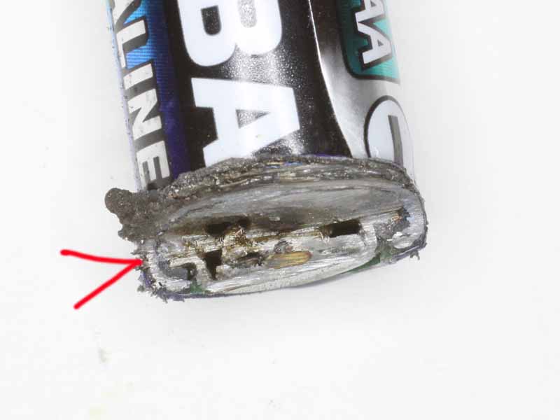
Above is a view of the -ve end of the battery, ground through to expose the inner structure.

The failed batteries have leaked corrosive electrolyte, and they have all split around the circumference of the battery in the region indicated by the red arrow above. The split is common half way or more around the cell, the green seal and remnant of the rolled over case is  there, split away from the main case and covered in corrosive electrolyte residual.

This is not a failure of the green seal material, but rather the case fails.

It fails either due to internal corrosion, os weakness of the forming process. It is not clear that this area should be exposed to electrolyte anyway, so the corrosion might result from some other internal failure that releases electrolyte.

Enough reason to remove them from all devices and NEVER use these cells again.

Mast ground rework

When I moved here about eight years ago, I quickly installed a small mast and associated ground system for the station. The grounding of the mast itself for lightning protection was a temporary solution, and less temporary than planned. This article documents the rework.

GroundRod01Above is the temporary solution. A 2.4m copper clad ground rod was driven into the clay, and a couple of short 25mm^2 tails connected to the mast tube. The long term solution was to be tidier and allow the mower / brushcutter to be used to trim grass without fouling the earth rod or cables.

The plan is to cut to bent top of the earth rod, drive it below ground level, and make a new tail of 35mm^2 (#2) cable and Cadweld it to the ground rod. Continue reading Mast ground rework

MFJ-993B on my G5RV with tuned feeder

This article is an analysis of why my recently acquired MFJ-993B will not match my multiband antenna system on most bands above 20m. The MFJ-993B replaces an Ameritron ATR-30 which was capable of matching the antenna system on all HF amateur bands.

A detailed analysis is performed 18.15MHz on the first problem band.

Configuration

The antenna system uses a tune feeder configuration.

G5rvTuneFeeder

The alternative tuned feeder arrangement described at (Varney 1958).

In this case, the open wire line is 9m of home made 450Ω line (2mm copper wires spaced 50mm air insulated), a 1:1 current balun and 0.5m of RG400 tail to the ATU.

A 470K 1W metal film resistor and a 2095-100 gas discharge tube in parallel are connected in parallel with the ATU antenna terminals to reduced static build up and modest transient protection.

Impedance was measured looking with a Rigexpert AA-600 into the cable end that plugs onto the ATU, at 18.15MHz is is 4.7-j69.5Ω.
Continue reading MFJ-993B on my G5RV with tuned feeder

Exploiting your antenna analyser #25

Find coax cable velocity factor using an antenna analyser without using SOL calibration

A common task is to measure the velocity factor of a sample of coaxial transmission line using an instrument without using SOL calibration.

Whilst this seems a trivial task with a modern antenna analyser, it seems to challenge many hams.

We will use a little test fixture that I made for measuring small components, and for which I have made test loads for SOL calibration. We will find the frequency where reactance passes through zero at the first parallel resonance of an O/C stub section, this is at a length of approximately λ/2 (a good approximation for low loss coaxial cables above about 10MHz).

We will use a little test fixture that I made for measuring small components, and for which I have made test loads for SOL calibration.

The text fixture used for this demonstration is constructed on a SMA(M) PCB connector using some machined pin connector strip and N(M)-SMA(F) adapters to connect to the instrument.

VfMeasurement01

Above is a pic of the test fixture with adapters (in this case on a AA-600). Continue reading Exploiting your antenna analyser #25

Exploiting your antenna analyser #24

Find coax cable velocity factor using an antenna analyser with SOL calibration

A common task is to measure the velocity factor of a sample of coaxial transmission line using an instrument that supports SOL calibration, an AIMuhf in this example.

Whilst this seems a trivial task with a modern antenna analyser, it seems to challenge many hams.

There are a thousand recipes, I am going to demonstrate just one that suits the instrument and application.

We will use a little test fixture that I made for measuring small components, and for which I have made test loads for SOL calibration. We will find the frequency where reactance passes through zero at the first parallel resonance of an O/C stub section, this is at a length of approximately λ/2 (a good approximation for low loss coaxial cables above about 10MHz).

The text fixture used for this demonstration is constructed on a SMA(M) PCB connector using some machined pin connector strip and N(M)-SMA(F) adapters to connect to the instrument.

VfMeasurement01

Above is a pic of the test fixture with adapters (in this case on a AA-600). Continue reading Exploiting your antenna analyser #24

NEC GM, GX tutorial

NEC requires the user to define a model structure as a set of geometry elements. It includes two powerful cards that make definition of the structure simpler and more reliable, they are the GM card for coordinate transformation and GX card for reflecting a structure in coordinate planes.

This tutorial demonstrates the use of these cards to define what might appear to be a fairly complex hypothetical NVIS antenna scenario quite simply, and more importantly, reliably. I say reliably because the logical definition of the model based on similar elements already defined, the more confident the developer can be that they are indeed similarly defined,  the differences are explicit, and that they are properly connected.

Screenshot - 03_09_16 , 10_22_56Above is a model to explore coupling from a tx antenna to a nearby rx antenna, The scenario contains 52 wire elements which one could naively define using 52 GW cards.

Instead, we will define it with far fewer GW cards and use model symmetry, rotation and translation to define the model. Continue reading NEC GM, GX tutorial

Post mortem review of a 144MHz combiner / splitter

This article is a post mortem review of a 144MHz splitter combiner that was made using RG6 coax. It is post mortem (ie post death) because the combiner was stored outdoors without checking that the connectors were protected from weather.

Fig01

The combiner was used successfully for over 10 years on a 144MHz four over four antenna system (above) without any maintenance problems.

Fig06

Above is a close up of the Tee point of the network. The coax cables are protected by HDPE sleeving to reduce the chance of damage at the hands of Sulphur Crested Cockatoos, in the event there was no damage.
Continue reading Post mortem review of a 144MHz combiner / splitter