Fan controlled by humidity sensor

I have a problem with machine tools getting condensation on them when conditions in the shed read dew point.

A possible solution being explored is to circulate air with a fan, possible inducting outside air, when humidity approaches condensing conditions.

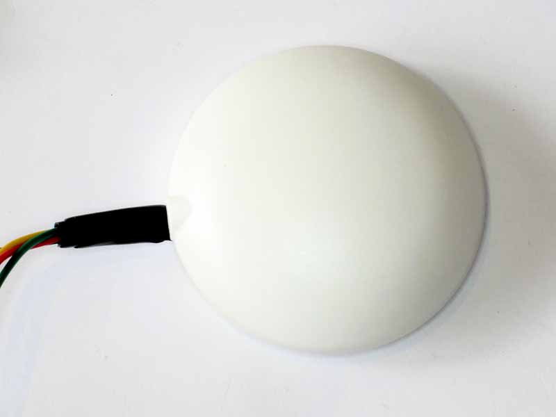
A quick search reveals the HDS10 resistive humidity sensor for a dollar or so on eBay.

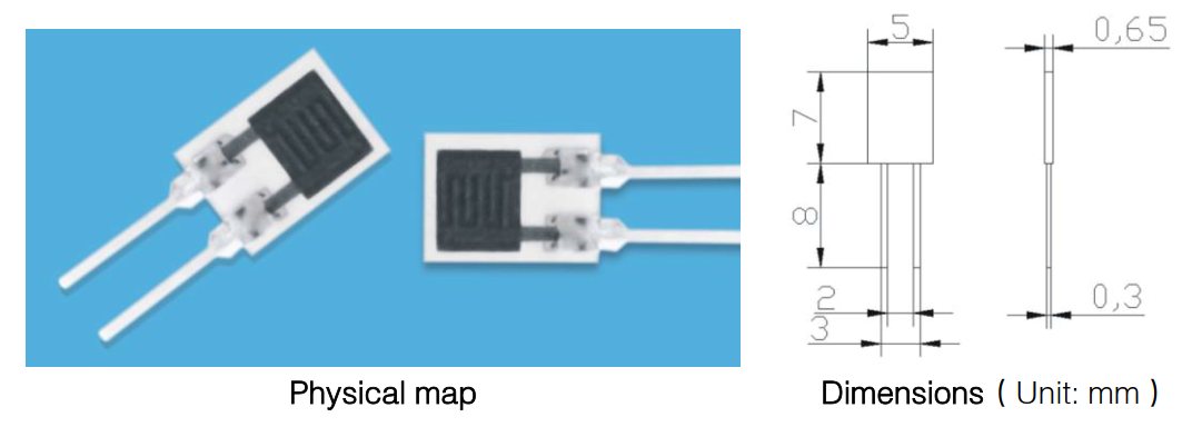
Above is the HDS10 humidity sensor.

Most low cost humidity sensors use a humidity dependent capacitive element, the HDS10 is different in being a humidity dependent capacitive element and is therefore simpler to use with microcontrollers with ADC input.

HDS10-02

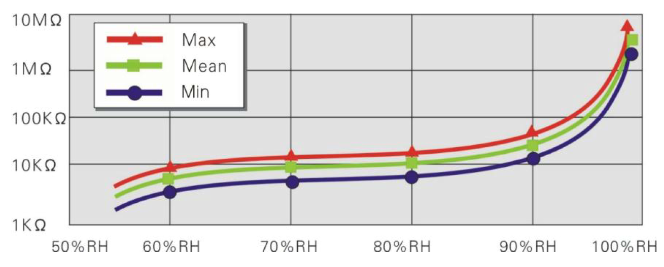
The above graph is from the datasheet. It is intended primarily for sensing high humidity (dew point, condensing conditions) which suits this application.
Continue reading Fan controlled by humidity sensor

Thinking about vibration forces from a bent prop adapter

A recent crash trying to tame the update from CF v1.10 to v1.12 did some damage to two prop adapters, bending them just above the lower flange causing axial runout. The weak point in these adapters is at the transition from the hollow tapered lower section to the solid threaded upper section.

PropAdapterRunout01Above is measurement of the runout on the lower part of the spinner with a propeller hub mounted. Total Indicated Runout (TIR) was measured at almost 0.5mm, lets call it 0.5mm, and runout from centre is therefore 0.25mm. Continue reading Thinking about vibration forces from a bent prop adapter

Cleanflight and PPM

The first widely used ‘digital’ communications protocol used with Remote Control (RC) models was PWM.

Though PWM is a generic term, the accepted timing was that a pulse width of 1000µs to 2000µs conveyed 0-100% of the proportional control. The the on-off nature of the PWM signal was discrete (digital), the duration of the pulse was stepless (ie not discrete), and since there was no shared time reference, the receiver’s interpretation of the signal may have error.

So, for a multichannel system, there would be one ‘signal’ wire for each channel, which gets to be a nuisance for lots of channels.

PPM (aka PPMSUM, CPPM) was an early protocol to multiplex multiple channels on one signal wire. The initial protocol description was of a frame comprising 500µs SPACE (S) followed by 500µs – 1500µs MARK (M) carrying the channel information as in the RC PWM protocol, then the same for the next channel and so on. These frames were repeated at a fixed frame repetition rate (FRR) of around 50Hz. Early implementations ‘defined’ this total frame duration variably, eg 18ms, 22.5ms, 28ms were popular. Continue reading Cleanflight and PPM

Review of inexpensive Chinese thermostat – STC-1000

This is a review of an inexpensive STC-1000 Chinese bang-bang  thermostat that was purchased on eBay for around A$12 complete with thermistor sensor and postage.

Above is the front view of the thermostat. There are many thermostats on the market with similar front panels, but they differ in internals and most importantly, performance and quality.

STC-1000-03

Above, the rating label is clear and informational, but it does not give the sensor parameters.  It is rated at 10A for resistive loads (AC-1), but it is doubtful that AC-3 motor loads of more than 20-30% of that should be used. Continue reading Review of inexpensive Chinese thermostat – STC-1000

Optimal Z0 for TLT sections challenge – a solution

Optimal Z0 for Guanella balun sections left the reader with a though exercise, a transmission line transformer used by PA0V in a 144MHz power amplifier output network.

Clip 206

The pair of tabs to the left are driven by FET drains, the upper pink centre conductor is grounded, the lower end connecting to C1 is the output to a nominal 50R load. The network shown near OUT is for fine load adjustment. There are two coax sections making this TLT, shields bonded all the way around and the centre conductors connected as shown. What is the optimal value of Z0 for each the coax sections?

PAdetail

Above is a pic of the PA, and we are looking at the network to the right of the dual FET. Continue reading Optimal Z0 for TLT sections challenge – a solution

Optimal Z0 for Guanella balun sections

A Guanella balun may have several sections, and they may be connected in parallel on one side and series on the other side so as to achieve nominal impedance transformation ratios other than 1.

The question is often asked, what is the optimal Z0 for these line sections?

Several answers exist in ham lore, but the answer is relatively simple and revealed by the most basic understanding of transmission lines.

If you do not want standing waves on a line section and its associated impedance transformation, then make sure that Z0=V/I… easy as that.

(Guanella 1944) explains it with examples:

Screenshot - 09_07_16 , 15_55_57

Note above that he refers to coil systems. He did not describe for instance (b) on a single core, a shared magnetic circuit which would be a single core system, but he states clearly two coil systems. (Sevick 2001) and lots of other hams say otherwise, but they are wrong. Continue reading Optimal Z0 for Guanella balun sections

Comparison of SimonK and BLHeli 14.6 on an Afro30 ESC

Plans are being made to build another copter using a Seriously Pro F3 Flight Controller, and drive options are being considered.

Since this is a high performance flight controller with faster loop times, and Oneshot125 is used on the ESCs for faster response, an ESC that exhibits fast response is warranted to fully explore the benefits of faster loop times.

Most stock ESCs are quite slow, though with replacement firmware they can perform much better.

Though I have dismissed BLHeli for several reasons in the past, I have a set of Hobbywing Skywalker 40A Silabs based ESCs which will run BLHeli and not SimonK, so review of the current version (14.6) of BLHeli is warranted.

Dowloading 55MB of bloatware and updating the firmware using a Silabs Sticktool / C2 interface (which itself is quite fast and convenient as I have added permanent cables for the C2 interface), reminded me of most of the bad things of BLHeliSuite. Despite falling foul of the traps too many times, I achieved the desired result
Afro30


This article documents some comparison tests of:

  • SimonK commit 1f75da384e5c83f83916aa752819ca6eed712565 afro_nfet.hex; and
  • BLHeli v14.6 for Hobbywing Skywalker 40A.

Continue reading Comparison of SimonK and BLHeli 14.6 on an Afro30 ESC

Can a hand held analyser be used to evaluate Insertion VSWR of a VSWR meter?

Some recent articles here used a two port analyser to evaluate Insertion VSWR of some coax switches, and it raises the question about application of a hand held analyser and Insertion VSWR of a VSWR meter.

(Duffy 2007) listed tests for evaluation of a VSWR meter:

Testing a VSWR meter

The tests here need to be interpreted in the context of whether the device under test (DUT) has only calibrated power scales, or a VSWR Set/Reflected mode of measurement, and whether directional coupler scales are identical for both directions.

  1. Connect a calibrated dummy load of the nominal impedance on the instrument output and measure the VSWR at upper and lower limit frequencies and some in between frequencies. The VSWR should be 1. (Checks nominal calibration impedance);
  2. Repeat Test 1 at a selection of test frequencies and for each test, without changing transmitter power, reverse the DUT and verify that repeat the forward/set and reflected readings swap, but are of the same amplitude (checks the symmetry / balance of the detectors under matched line conditions).
  3. Connect a s/c to the instrument output and measure the VSWR at upper and lower limit frequencies and some in between frequencies. The VSWR should be infinite. (Discloses averaging due to excessive sampler length);
  4. Connect an o/c to the instrument output and measure the VSWR at upper and lower limit frequencies and some in between frequencies. The VSWR should be infinite. (Discloses averaging due to excessive sampler length);
  5. Connect a calibrated wattmeter / dummy load of the nominal impedance on the instrument output and measure calibration accuracy of power / ρ / VSWR scales at a range of power levels in both forward and reflected directions (Checks scale shape and absolute power calibration accuracy).
  6. Repeating Test 1 additionally with a calibrated VSWR meter connected to the input to the DUT, and measure the VSWR caused by the DUT at a range of test frequencies (Checks Insertion VSWR).

It is not unusual for low grade instruments to pass Test 1, but to fail Test 6 (and some others, especially Test 3 and Test 4) towards the higher end of their specified frequency range.

Item 6 in the list was to evaluate the Insertion VSWR. Continue reading Can a hand held analyser be used to evaluate Insertion VSWR of a VSWR meter?

Dataflash on NAZE32

The Acro NAZE32 flight controller ships without a dataflash chip, which is so shortsighted of the designer / manufacturer. Many users will not be at all interested in Baro or Magnetometer which come on the deluxe version, but the dataflash is so useful in tuning a copter.

Unfortunately, the designer put pads on the rev5 board for 150mil SOIC-8 chips (SOICN), but lots of dataflash chips are in 208mil packages (SOICW) and all the large capacity chips are SOICW. Rev6 boards appear to have pads that will suit both sizes… but then the Acro comes with dataflash, even if small.

If you are happy to install a 2Mb dataflash chip, buy a SOICN package and your job is easy.

I installed a 64Mb Winbond chip (W25Q64FVSIG), they are easy to find on eBay for a dollar or so. (You will also need a 10nF ceramic 0603 cap).

If you want to install a SOICW package… Continue reading Dataflash on NAZE32

U-BLOX LEA-6T GPS module – for experiments

This article documents a LEA-6T module build for general experiments.

The LEA-6T is an inexpensive GPS module (~$40 at time of purchase, but getting cheaper) that can supply raw pseudo range data.

LEA-6T02

The module above is supplied for use on UAVs of various kinds, and came complete with a plastic radome and cables to suit an APM copter. The module also contains a 3D compass (magnetometer) which is not used here.

LEA-6T03

Above is the internals of the module with a custom cable to pick up just the RS232-TTL signals from the GPS (and supply 5V). The connector is a 8pin Hirose DF13. Continue reading U-BLOX LEA-6T GPS module – for experiments