Cooling an IC2200H

IC2000HCooling2

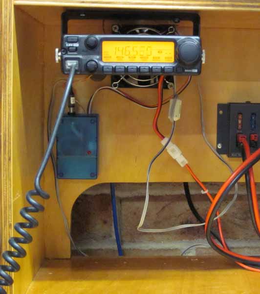
I have an IC2200H mounted on my operating table with 25mm clearance above the radio and ample room for convection currents to assist in heat removal. It is concerning that the case temperature reaches temperatures that are not safe to touch, temperatures in excess of 75° (55° above ambient) have been measured and that has not triggered the internal temperature protection… so it could get hotter still!

Whilst it might take a while for the radio to reach high temperatures, in the long term, it must dissipate around 139W when transmitting on HIGH power setting and at ambient temperatures as high as 35° in the shack. (Rated input is 15A at 13.6V for 65W out, leaving 139W of heat to be dissipated.)

This is one of those high power mobile radios that advertises no fan as an advantage, but it is clearly not up to the task!

The objective of this change is to keep the external parts below 60°, the (ASTM standard C1055  1999) 5 second human skin burn threshold.

Continue reading Cooling an IC2200H

Mag loop or radiating dummy load?

There is a seemingly endless series of articles on small transmitting loops on the cheap.

(eHam 2014) is another, it describes a so-called magnetic loop for transmitting on 14.2Mhz using 4.57m of 2.6mm copper wire for the main loop. The author reports the bandwidth of the finished antenna as 100kHz. One of the claimed benefits is that with such wide bandwidth, a variable tuning capacitor is not required.

Continue reading Mag loop or radiating dummy load?

Designing high performance VHF/UHF receive systems – Part 1

G/T

A metric that may be used to express the performance of an entire receive system is the ratio of antenna gain to total equivalent noise temperature, usually expressed in deciBels as dB/K. G/T is widely used in design and specification of satellite communications systems.

G/T=AntennaGain/TotalNoiseTemperature 1/K

Example: if AntennaGain=50 and TotalNoiseTemperature=120K, then G/T=50/120=0.416 1/K or -3.8 dB/K.

Continue reading Designing high performance VHF/UHF receive systems – Part 1

VK2OMD ambient noise measurement 144MHz – 20140217

I made a measurement of ambient noise on 144MHz this morning using the technique described at (Duffy 2009).


TS2000NF

First step is to recheck the NF of the receiver. The TS2000 is getting a little tired, NF=8.3dB.

The technique calculates ambient noise from the variation in receiver output noise of a receiver of known Noise Figure with the insertion of a known input attenuator. The receiver output noise was measured using NFM (Duffy 2007) which allowed integration over 20s for high resolution measurement.

046 Continue reading VK2OMD ambient noise measurement 144MHz – 20140217

VK2OMD G5RV with tuned feeder – line loss

The G5RV Inverted V antenna system at VK2OMD is fed with 9m of home made open wire transmission line using 2mm diameter copper wires spaced 50mm giving a line with characteristic impedance of 450Ω. (Varney 1958) described the tuned feeder configuration of his popular G5RV antenna system.

Continue reading VK2OMD G5RV with tuned feeder – line loss

BLHeli v11.0 on APM X450 quad

I had some Skywalker 40A with BLHeli v11 spare from the tricopter project, so I have put them on the APM X450 quad for a trial.

SW-prog

The BLHeli beacon is really annoying, so I turned it off. Otherwise it is a pretty basic Multi BLHeli configuration.

The ESCs were throttle calibrated using APM’s all at once procedure… but it didn’t work as expected, the motors remained stopped when armed. A lot of fiddling around to find some parameter changes did not work until power was cycled. Set MOT_SPIN_ARMED=200, THR_MIN=220.

Initial tests in stable, alt hold and loiter modes have been good.


Small transmitting loop review

I saw a recent ‘maker’ video describing a small transmitting loop for 40m.

The loop used a 3m length of 19mm copper pipe formed into a circle, and at the gap where the ends almost meet, a tuning capacitance is synthesised using coaxial cable.

Screenshot - 15_02_2014 , 12_06_57

Above is a screen shot from Reg Edwards loop design program. It calculates the radiation resistance at 0.005Ω, loss resistance of the loop at 0.035Ω, capacitance to resonate it of 206pF (Xc=108Ω), and a bandwidth of 3.2kHz.

Continue reading Small transmitting loop review

ATU voltage verification

I described a method for designing antenna systems to avoid excessive voltages in baluns and ATUs at (Duffy 2011) .

This article reports post implementation measurements of an antenna system designed using that method and using a G5RV Inverted V with tuned feeder and ATR-30 ATU with integral 1:1 current balun. The tuned feeder is a home-made line section of 2mm diameter copper conductors spaced 50mm, and 9m in length. An additional 0.5m of 135Ω line connects from the antenna entrance panel to the ATU.

Continue reading ATU voltage verification

A look at internal losses in a typical ATU

This article explores the loss that may be encountered in an ATU in a practical setting.

The load is a G5RV with tuned feeders operating at 3.6MHz. The tuned feeder is 9m of open wire line of characteristic impedance 450Ω, and the impedance seen by the ATU is around 40-j150Ω, this is not a particularly onerous load.

MFJ949E02

Continue reading A look at internal losses in a typical ATU

An inexpensive medium power tuner current balun for HF using Jaycar parts

This is a project to design and build a Guanella 1:1 (current) balun suited for up to 100W on HF with wire antennas and an ATU.

For use with a tuner, the most important design criteria are:

  • high voltage withstand;
  • high common mode impedance;
  • power handling.

Continue reading An inexpensive medium power tuner current balun for HF using Jaycar parts