Improving quadcopter stability at very low throttle using Complementary PWM

This article documents a case study in use of Complementary PWM (COMP_PWM) to improve quadcopter stability at very low throttle.

An observation of two quadcopters of 450 size running several releases of Cleanflight and now Betaflight 3.01 is a loss of stability at very low throttle opening.

This is not uncommon for several reasons, and there is ‘airmode’ in both firmwares to address the problem that motors at minimum speed cannot be slowed further. Experience with airmode on Cleanflight up to v1.14.1 was that it raised throttle so much that descents were extremely slow sometimes, certainly never quick, and its use was discontinued.

I have since abandoned Cleanflight due to unresolved flight problems, lack of migration facility from version to version, and the quiet removal of the backup and restore facility.

The objective of this study was to explore the effect of enhanced motor braking with COMP_PWM on basic angle mode loop stability at low rpm.

Test scenario

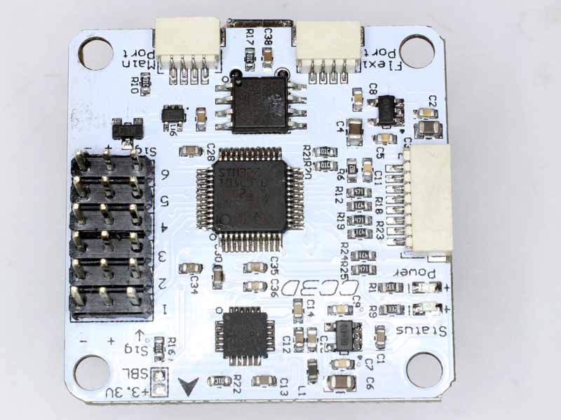
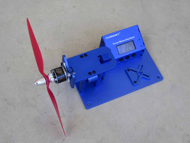
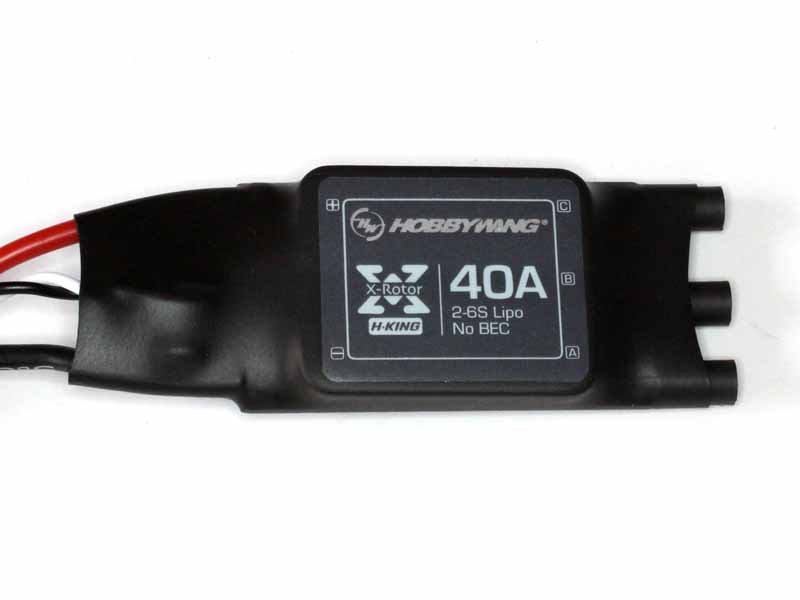
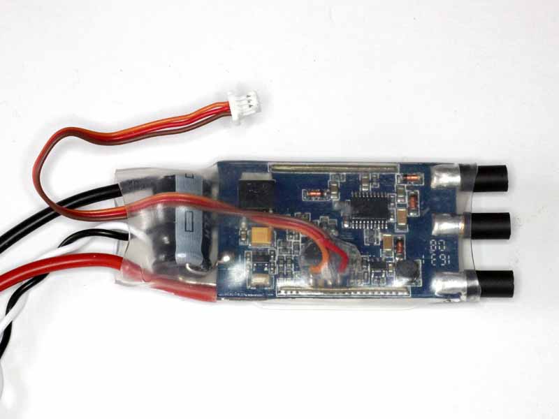
The study uses a BC3530 1100Kv motor with 11×4.7 SF propeller, F-30A ESC with SimonK (1e4c01782eff85da3971f628a3bd599b7a0725eb) with COMP_PWM enabled.

Tests were conducted with a script that I use consistently with asrg and eLogger to capture current and rpm, and all tests conducted at similar pressure, temperature and humidity, altitude is 700m.

Test results

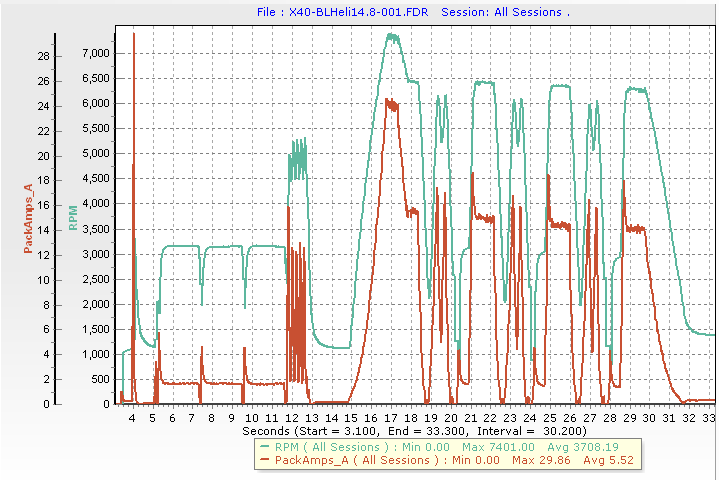
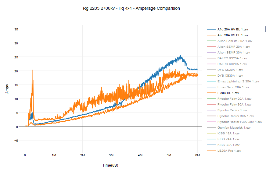
One of the effects of COMP_PWM is stronger braking of the motor when throttle is reduced. In multi-rotor application, the motor braking under COMP_PWM is dwarfed by the propeller load at maximum rpm, but propeller torque falls as the square of rpm and at lower speeds motor braking becomes more significant.

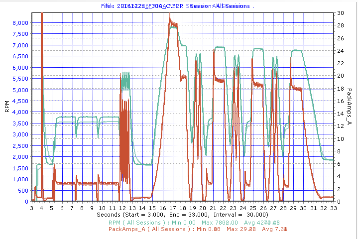
Above is a graph of the drive response with a non-COMP_PWM response feint overlay. It can be seen at 13s, that under rapid deceleration, the COMP_PWM response differs, lets zoom in on that. Continue reading Improving quadcopter stability at very low throttle using Complementary PWM

Max thrust: Hobbywing XRotor 40A (MkII) vs BLHeli Hobbywing XRotor 40A (MkII) vs SimonK Hobbyking 9261000003 40A

This article documents a comparative thrust test of a stock Hobbywing X-Rotor 40A, Hobbywing X-Rotor 40A with BLHeli firmware and a Hobbyking 9261000003 40A with SimonK firmware on a medium sized motor at wide open throttle (WOT).

Battery is 3S fully charged.

Motor is a Turnigy Propdrive 28-26S 1100kV;

Propeller is a 9×4.7 SF;

Stock Hobbywing configuration

The X-Rotor 40A out of the box then a throttle cal for 1030/2000 performed.

BLHeli configuration

The X-Rotor 40A is configured with BLHeli v14.8 MULTI, default BLHeli config, then a throttle cal for 1030/2000 performed.

SimonK configuration

The Hobbyking 9261000003 40A is flashed with SimonK’s tgy Hobbyking 9261000003 40A (1e4c01782eff85da3971f628a3bd599b7a0725eb) 15/10/2015.


Above, the motor and prop used for the test.

Maximum measured thrust results:

  • X-Rotor 40A with stock Hobbywing firmware: 850g;
  • X-Rotor 40A with BLHeli: 870g;
  • Hobbyking 9261000003 40A with SimonK: 950g

BLHeli Hobbywing XRotor 40A (MkII) vs SimonK Hobbyking 9261000003 40A

This article documents a comparative test of a Hobbywing X-Rotor 40A with BLHeli firmware and a Hobbyking 9261000003 40A with SimonK firmware.

The motor is an inexpensive BC3530-14 1100kV motor loaded with a 11×4.7″ slowfly Gemfan propeller, power input to the drive is a little over 300W at wide open throttle.

Battery is 3S fully charged.

Tests were conducted with a script that I use consistently with asrg and eLogger to capture current and rpm, and all tests conducted at similar pressure, temperature and humidity, altitude is 700m.

BLHeli configuration

The X-Rotor 40A is configured with BLHeli v14.8 MULTI, default BLHeli config, then a throttle cal for 1030/2000 performed.

SimonK configuration

The Hobbyking 9261000003 40A is flashed with SimonK’s tgy Hobbyking 9261000003 40A (1e4c01782eff85da3971f628a3bd599b7a0725eb) 15/10/2015.

FET dead times are set rather high at 2000s to be compatible with the slower F40-A. Previous tests have indicated that 1200µs dead time for high and low FETs suits the 9261000003.

Test results

Above, the test run of Hobbywing X-Rotor 40A with BLHeli v14.8 firmware. Continue reading BLHeli Hobbywing XRotor 40A (MkII) vs SimonK Hobbyking 9261000003 40A

BLHeli 14.8 damped light and active freewheeling

Aficionados of BLHeli call out the benefits of “damped light” and “active freewheeling”, terms coined by BLHeli’s author.

Since these are terms invented by BLHeli, so you might wonder whether they are truly innovative or just marketing hype for existing techniques.

Lets go to the BLHeli manual for an explanation.

Pwm damped light mode adds loss to the motor for faster retardation. Damped light mode always uses high pwm frequency. In damped light mode, two motor terminals are shorted when pwm is off

Taking the last statement first, in fact, what happens that as that during the OFF phase of the PWM drive, the high side FETs at both ends of the winding are turned ON. One FET is on for the whole phase, and the other one switches on a short time after its corresponding low side FET turns off. The short time is to allow the low side FET to cease conducting, otherwise both high and low side FETs would conduct at the same time, a current from battery +ve to -ve via the two FETs. There is a corresponding pause at the end of the PWM phase. The time delays allowed depend on the driver circuitry and FET performance, they are specified in the firmware  for a specific and don’t necessarily apply to a pin compatible ESC.

This technique is known in the wider community as COMPLEMENTARY PWM, a very standard technique. Continue reading BLHeli 14.8 damped light and active freewheeling

Hobbywing XRotor 40A (MkII)

Above is the Hobbywing (HW) X-Rotor 40A (BECless) purchased from Hobbyking. It lacks the authenticity markings promoted by Hobbywing, is it a clone? Who knows, it is Chinese.

The X-Rotor 40A was tested in its default configuration, there was no reason to change commutation timing.

Hobbywing enjoys a reputation as a quality product, a cut above the no-name products but his ESC was purchased for about A$16 + shipping, which is really a budget price for a 6S 40-60A BECless (or OPTO) ESC.

Tests were conducted with a script that I use consistently with asrg and eLogger to capture current and rpm, and all tests conducted at similar pressure, temperature and humidity, altitude is 700m.

BLHeli configuration


Above is a X-Rotor 40A modified with a permanent C2 interface cable for programming the MCU. The cable has a JST-SH1.0 connector (purchased as HK 258000026) to plug into the after market Tool Stick clone (HK 289000003). The wires from the left are orange , NC, brown and red. (Orange, Red and Brown wires correspond to Black (GND), White (C2D) and Red (C2CK) dots on BLHeli documentation.) A small dot of hot melt adhesive is applied after soldering the wires to the PCB pads, and the cable folded down into the adhesive (to prevent fatigue and breakage of wires). The whole thing will be served over by clear heat shrink.
Continue reading Hobbywing XRotor 40A (MkII)

Robust programming of Silabs based BLHeli ESCs

This article describes a solution for robust and reliable ‘production’ programming of Silabs based BLHeli ESCs.

The intention is to test and tune the BLHeli configuration, save the configuration in some form, and a scripted solution to programming multiple ESCs now and later replacements with high confidence that they are exactly matching configurations.

There does not appear to be any batch facility for writing flash using the BLHeli bootloader, nor does it appear that BLHeliSuite can save the relevant hex files for later use, so excluding use of the BLHeli bootloader.

The configuration data is held in a block of flash memory labelled EEPROM in the source code. It is not actually EEPROM, the MCU does not have EEPROM, but for consistency the block will be referred to as EEPROM in this article.

Having tested and tuned the configuration using BLHeliSuite, the EEPROM block from the test ESC is read back using Silabs Flash Programming Utility (FPU) and a toolstick attached to the ESC’s C2 interface.

Above, reading the EEPROM block.

The EEPROM block is them merged over the distribution hex file to create a custom hex file for repeated use. Continue reading Robust programming of Silabs based BLHeli ESCs

RC electric drive noise

The website Mini Quad Test Bench by Ryan Harrell contains a growing set of test results for motors and ESCs.

In respect of ESCs, it appears to use BLHeli unless the ESC is incompatible in which case the proprietary firmware is used.

The configurations are targeted mainly at the mini quad racer part of the market, and the requirements for different size copters and different applications varies significantly.

The site contains an online editable graph facility that allows customisation of the graph.

Screenshot - 14_08_16 , 09_33_03

Above is a graph of current vs time for a uniform ramp servo input, and I have disabled most of the ESC types for clarity, selecting just the first two on the list and one which I use (F-30A). Continue reading RC electric drive noise

Thinking about vibration forces from a bent prop adapter

A recent crash trying to tame the update from CF v1.10 to v1.12 did some damage to two prop adapters, bending them just above the lower flange causing axial runout. The weak point in these adapters is at the transition from the hollow tapered lower section to the solid threaded upper section.

PropAdapterRunout01Above is measurement of the runout on the lower part of the spinner with a propeller hub mounted. Total Indicated Runout (TIR) was measured at almost 0.5mm, lets call it 0.5mm, and runout from centre is therefore 0.25mm. Continue reading Thinking about vibration forces from a bent prop adapter

Cleanflight and PPM

The first widely used ‘digital’ communications protocol used with Remote Control (RC) models was PWM.

Though PWM is a generic term, the accepted timing was that a pulse width of 1000µs to 2000µs conveyed 0-100% of the proportional control. The the on-off nature of the PWM signal was discrete (digital), the duration of the pulse was stepless (ie not discrete), and since there was no shared time reference, the receiver’s interpretation of the signal may have error.

So, for a multichannel system, there would be one ‘signal’ wire for each channel, which gets to be a nuisance for lots of channels.

PPM (aka PPMSUM, CPPM) was an early protocol to multiplex multiple channels on one signal wire. The initial protocol description was of a frame comprising 500µs SPACE (S) followed by 500µs – 1500µs MARK (M) carrying the channel information as in the RC PWM protocol, then the same for the next channel and so on. These frames were repeated at a fixed frame repetition rate (FRR) of around 50Hz. Early implementations ‘defined’ this total frame duration variably, eg 18ms, 22.5ms, 28ms were popular. Continue reading Cleanflight and PPM