Receive only antenna for 160m – maximum receiver NF for SND

This article explores the design / analysis of a passive receive system for the 160m band, determining the maximum receiver noise figure (NF) to achieve a specified maximum S/N degradation (SND) by receiver internal noise.

For explanation of the metric Signal to Noise Degradation (SND), see Signal to noise degradation (SND) concept.

The antenna data table given uses a tabulated average gain for a set of interesting 160m antennas published by Tom Rauch (W8JI) at https://www.w8ji.com/receiving.htm . Read the whole article, it is interesting and relevant.

External noise is estimated using ITU-R P.372-16, and results are tabulated for the five noise environment categories used in ITU-R P.372-16.

The example and calculations assume linear systems, if there is significant nonlinearity that gives rise to significant IMD, IMD noise depends on the specific scenario (including receive spectrum) and is not captured by this analysis.

Maximium receiver NF for given SND

Let us assume that noise arrives equally from all directions. In that case, the average gain of the antenna is used to determine the noise power captured, \({Gain}_{avg}={Gain}_{max}-\text{Directivity}\).

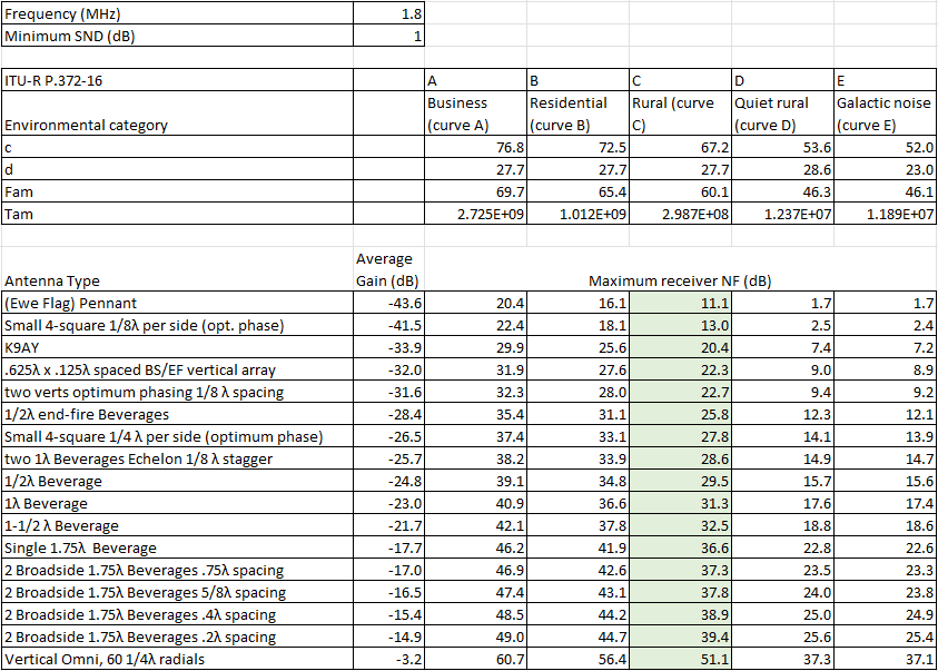
The table above uses Rauch’s tabulated average gain for a range of 160m antennas, and calculates the maximum receiver NF to achieve the specified 1dB maximum SND. Continue reading Receive only antenna for 160m – maximum receiver NF for SND

Receive only antenna for 160m – K9AY matching and performance discussion

This article explores the design / analysis of a passive receive only antenna, a K9AY loop, for the 160m band (1.8MHz).

The example and calculations assume linear systems, if there is significant nonlinearity that gives rise to significant IMD, IMD noise is not captured by the analysis.

Results are for the scenarios calculated and may not be extensible to different scenarios.

Another caveat: I have reservations about transmission line modelling in SimNEC, especially for composite conductors, but for the purposes of the discussion, assume that it is reasonably correct.

Above is the K9AY loop from a model by W7EL.

Design objective

The objective here is to design a receive only antenna system that can be relatively remote from local noise sources (like house wiring), and captures enough external signal and noise that the receiver internal noise does not degrade S/N too much. Continue reading Receive only antenna for 160m – K9AY matching and performance discussion

Receive only antenna for 160m – matching and performance discussion – improved SimNEC model

This article is a follow on from Receive only antenna for 160m – matching and performance discussion. It develops a SimNEC model that imports the loop impedance, and transforms it with an ideal transformer to quickly find an optimal transformer ratio and predict system losses.

Results are for the scenarios calculated and may not be extensible to different scenarios.

Another caveat: I have reservations about transmission line modelling in SimNEC, especially for composite conductors, but for the purposes of the discussion, assume that it is reasonably correct.

Above is the SimNEC model, it assumes reciprocity of the antenna system. Continue reading Receive only antenna for 160m – matching and performance discussion – improved SimNEC model

Receive only antenna for 160m – matching and performance discussion – 8000pF?

A reader of Receive only antenna for 160m – matching and performance discussion referred me to an online discussion with a simpler solution.

A couple of quotes from posters…

It almost doesn’t matter what the actual receiver Zin is. What matters is the 100ft of 50 or 75 Ohm coax that is used to get the Rx-only antenna signal from where the antenna is placed to the receiver.

and…

That’s what I thought, also.

A few hundred feet of coax can be ~8000 pF of parallel capacitance which should short out signals by having only about 11 Ohms of reactance.

So the gist of this is that:

  • receiver Zin does not matter;
  • the 100′ of coax or 300′ of coax matters; and
  • 300′ of coax can be adequately represented by a shunt capacitance of 8000pF.

Receiver input impedance is not necessarily a tightly controlled parameter, but it is measurable, so lets take a real example.

IC7300 example

Let’s measure Zin of an example IC7300 around the 160m band.

Above is Zin plotted from a saved .s1p file. At 1.85MHz, Zin=56.2-j5.4Ω, a little off nominal, but pretty close (VSWR50=1.35). The dotted line is X and the dashed line is R, ignore the solid line… it is for people who don’t understand impedance. Continue reading Receive only antenna for 160m – matching and performance discussion – 8000pF?

VNA fixture for measuring Zcm of a common mode choke – twisted pair wound

VNA fixture for measuring Zcm of a common mode choke – coax wound discussed issues with common ham practice for measuring coax wound common mode chokes.

The article left readers with some homework:

  • Does the same thing occur if the core is wound with twisted pair that is well represented as a uniform two wire transmission line?
  • Are the resistors beneficial?
  • Do they degrade fixture behavior?
  • Then, why are the used so often?

This article addresses those questions.

Does the same thing occur if the core is wound with twisted pair that is well represented as a uniform two wire transmission line?

Let’s treat the common mode choke as a black box with two input terminals at left and two output terminals at right with voltages as annotated above. Continue reading VNA fixture for measuring Zcm of a common mode choke – twisted pair wound

Receive only antenna for 160m – matching and performance discussion

This article explores the design / analysis of a passive receive only antenna for the 160m band (1.8MHz).

The example and calculations assume linear systems, if there is significant nonlinearity that gives rise to significant IMD, IMD noise is not captured by the analysis.

Results are for the scenarios calculated and may not be extensible to different scenarios.

Another caveat: I have reservations about transmission line modelling in SimNEC, especially for composite conductors, but for the purposes of the discussion, assume that it is reasonably correct.

The example antenna is a K6SE 14’x29′ Pennant optimised for 160m.

Design objective

The objective here is to design a receive only antenna system that can be relatively remote from local noise sources (like house wiring), and captures enough external signal and noise that the receiver internal noise does not degrade S/N too much. Continue reading Receive only antenna for 160m – matching and performance discussion

VNA fixture for measuring Zcm of a common mode choke – coax wound

A common online question is what sort of fixture is appropriate to measure the common mode impedance of a common mode choke.

Above is a screenshot from a Youtube video by Trx Lab, probably about 2016 vintage. I see many problems with the fixture, lets start with the resistors. Continue reading VNA fixture for measuring Zcm of a common mode choke – coax wound

Does RBN give a reliable metric for comparing antennas – more detail

Does RBN give a reliable metric for comparing antennas? gave an example of signal strength measurement and the effect of fading over time.

This article goes into a little more depth on the subject using a further data capture of 600 measurements 10s apart.

Above is a plot of signal strength of an 80m A1 Morse (CW) beacon measured in 20Hz bandwidth over 100min (a terrestrial path of length 105km). Continue reading Does RBN give a reliable metric for comparing antennas – more detail

Reconciliation of transmitter power, EIRP, received signal strength, antenna factor, ground wave propagation etc @ 576kHz

This article reconciles measurements with path predictions for a MW AM transmitter on 576kHz. The techniques used could be used to validate / assess the performance of a transmitter.

Source

The source is a MF AM transmitter on 576kHz located about 74km distant.

Above is the station data from the ACMA licence register. Conveniently it gives the EIRP as 132kW, we would expect something a little less than 150kW from the nominal 50kW transmitter, system efficiency calculates to 80%.

The EIRP would have been calculated from a set of field strength measurements at the time of commissioning. Continue reading Reconciliation of transmitter power, EIRP, received signal strength, antenna factor, ground wave propagation etc @ 576kHz

Does RBN give a reliable metric for comparing antennas?

I see that lots of hams depend on HF RBN to compare to antennas, or to compare before and after a change.

Experience says that A/B comparisons on HF are subject to variation in Ionospheric propagation paths, and that variation can be wide in range and rapid.

An example

Above is a plot of signal strength of an 80m A1 Morse (CW) beacon measured in 20Hz bandwidth over 15min snapshot (a terrestrial path of length 105km). Continue reading Does RBN give a reliable metric for comparing antennas?