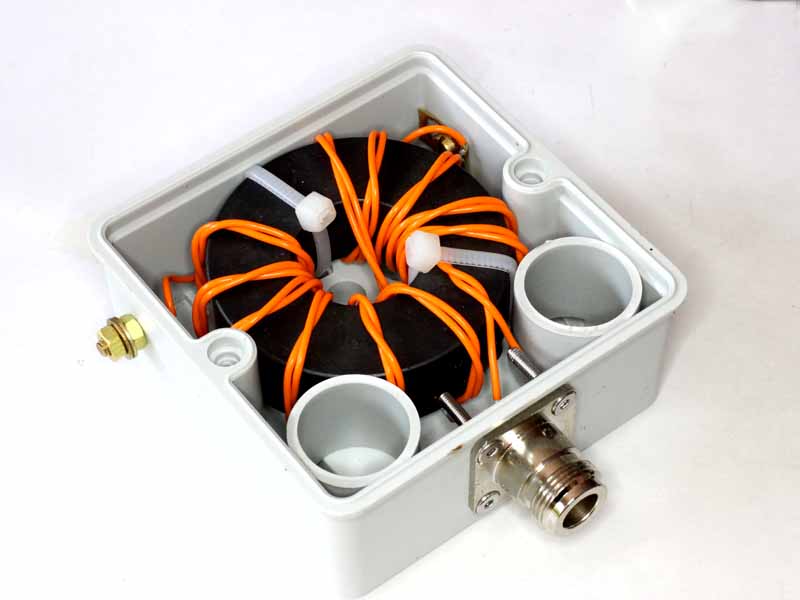
The article End Fed Half Wave matching transformer – 80-20m laid out a design for a EFHW transformer based on the readily available FT240-43.

This article builds an NEC model for an EFHW antenna at 3.6MHz incorporating a realistic model of the above transformer.
NEC provides for a NT card characterising a two port network using Y parameters.
Y parameter model for the transformer
The Y parameter model is based on measured input impedance with port 2 open circuit, and short circuit, and the observed turns ratio.
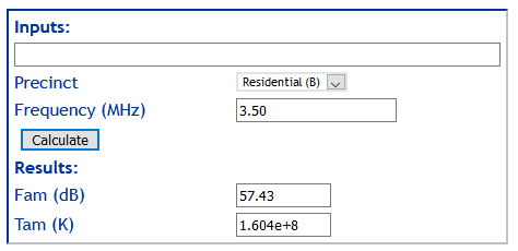
Impedance was measured with the transformer at 3.6MHz using an AA-600.
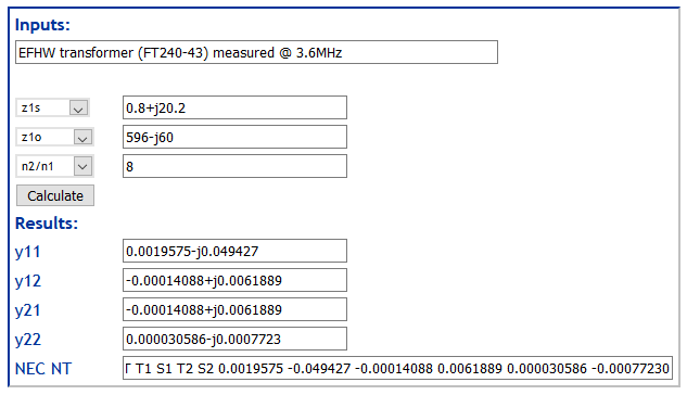
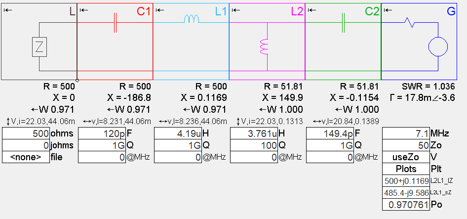
Above, the calculated Y parameter model including a prototype NT card. This model captures the various loss components of the transformer, mainly magnetising loss, at 3.6MHz. Continue reading FT240-43 matching transformer for an EFHW – NEC model at 3.6MHz